Table of Contents
Advertisement
Quick Links
Advertisement
Table of Contents
Troubleshooting

Subscribe to Our Youtube Channel
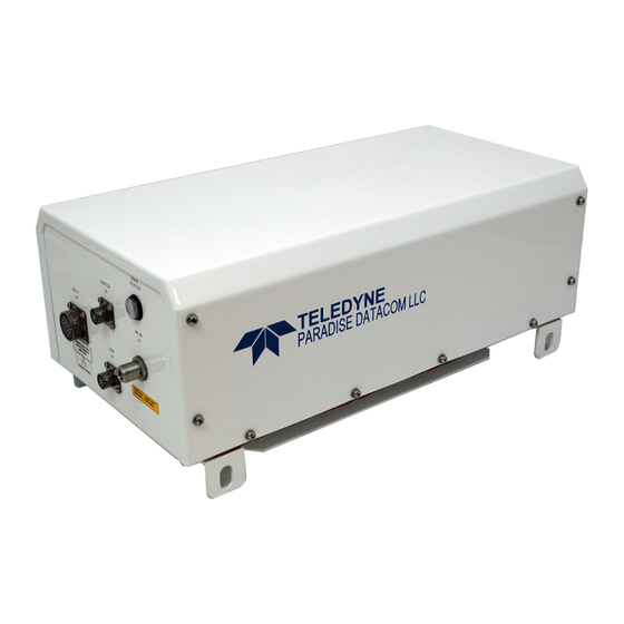
Related Manuals for Teledyne Compact Outdoor SSPA


Summary of Contents for Teledyne Compact Outdoor SSPA
- Page 1 Compact Outdoor Solid State Power Amplifier Operations Manual Teledyne Paradise Datacom LLC Phone: (814) 238-3450 328 Innovation Blvd., Suite 100 Fax: (814) 238-3829 State College, PA 16803 USA Web: www.paradisedata.com Email: sales@paradisedata.com 208495 REV F ECO 17951 07/24/2015...
- Page 2 (SSPAs), Low Noise Amplifiers (LNAs), Block Up Converters (BUCs), and Modem products. Operating out of two primary locations, Witham, United Kingdom, and State College, PA, USA, Teledyne Paradise Datacom has more than a 20 year history of providing innovative solutions to enable satellite uplinks, battlefield communications, and cellular backhaul.
-
Page 3: Table Of Contents
3.1 Port J4 Pin-Outs ....................28 3.1.1 Amplifier Enable (Mute/Unmute) (J4) ............ 30 3.1.2 Gain Adjust Input (J4) ................30 3.1.3 Alarms (J4) .................... 30 3.1.3.1 Summary Alarm (J4) Form C Contacts ........30 Operations Manual, HPA2, Compact Outdoor SSPA 208495 REV F... - Page 4 6.1.3 Input Return Loss ................. 62 6.1.4 Output Return Loss ................62 6.1.5 Intermodulation Distortion ..............63 6.1.6 Power Requirements ................63 6.1.7 Earth Ground ..................64 6.1.8 Sample Port ..................64 208495 REV F Operations Manual, HPA2, Compact Outdoor SSPA...
- Page 5 9.3.1 1:1 Fixed Phase Combined System with L-Band Input Components ..99 9.3.2 Signal Box Assembly ................99 9.3.3 Redundant BUC Operation ..............99 9.3.4 Adjusting the Phase Combining ............99 9.4 1:2 Fixed Phase Combined Systems ..............101 Operations Manual, HPA2, Compact Outdoor SSPA 208495 REV F...
- Page 6 11.0 Overview, Universal Handheld Controller ............141 Appendix A: Quick Start Cable ..................143 Appendix B: Alternate System Configurations ............. 145 Appendix C: Maintenance Switch Mode ................ 147 Appendix D: Documentation ................... 149 208495 REV F Operations Manual, HPA2, Compact Outdoor SSPA...
- Page 7 Figure 3-8: RS-232 Quick Start Cable, 207998 ..............32 Figure 3-9: Universal M&C Add Unit menu ................36 Figure 3-10: Add Compact Outdoor SSPA window, via Serial or Internet ......36 Figure 3-11: Universal M&C Status Window ................ 37 Figure 3-12: Fault Indicators ....................38 Figure 3-13: Universal M&C, Settings .................
- Page 8 Figure 8-7: M&C Program “SSPA Settings” window ............76 Figure 8-8: Adding a SSPA Monitor and Control Window ............ 78 Figure 8-9: Add New Compact Outdoor SSPA window ............79 Figure 8-10: Individual SSPA Operation Window ..............79 Figure 8-11: Universal M&C, Add Unit Menu Tree ............... 80 Figure 8-12: Universal M&C, Add 1:1 Redundant System Window ........
- Page 9 Table 10-10: System Threshold Data Values ..............117 Table 10-11: System Condition Addressing ............... 118 Table 10-12: OSI Model for Compact Outdoor SSPA Ethernet IP Interface ...... 125 Table 10-13: Detailed Settings for CO SSPA mode (Device Type=2) ....... 134 Table 10-14: Detailed Thresholds ..................
- Page 10 THIS PAGE INTENTIONALLY LEFT BLANK 208495 REV F Operations Manual, HPA2, Compact Outdoor SSPA...
-
Page 11: Section 1: General Information
Section 1: General Information 1.0 Introduction This section provides the general information for the Teledyne Paradise Datacom LLC line of Compact Outdoor Solid State Power Amplifiers. The Compact Outdoor SSPA has been designed and manufactured to be an extremely robust and reliable amplifier. It is well suited for harsh outdoor environments. -
Page 12: Equipment Supplied
Quick Start Serial (RS-232 / RS-485) Communication Cable, L207998-2 • Product Guide CD with SSPA Monitor & Control Software • Operations Manual, HPA2, Compact Outdoor SSPA (208495; this manual) • M&C (J4) Mating Connector, MS3116F18-32P • Waveguide gaskets (dependent on frequency band) •... -
Page 13: Comparisons Between Standard And Mini Compact Outdoor Sspas
• Slight variation in protocol • No analog gain control on J4 in Mini Compact Outdoor SSPA • No RF Power Detector analog output on J4 in Mini Compact Outdoor SSPA • No Low RF Fault output on J4 in Mini Compact Outdoor SSPA •... - Page 14 THIS PAGE INTENTIONALLY LEFT BLANK 208495 REV F Operations Manual, HPA2, Compact Outdoor SSPA...
-
Page 15: Section 2: Installation
1 (814) 238-3829 2.2 Connector Pin-Outs The following section details the connector pin-outs for the Mini Compact Outdoor SSPA. Figure 2-1 shows the overall dimensioned outline of a Compact Outdoor Amplifier. The connector locations can be found in Figures 2-2 through 2-4. -
Page 16: Rf Input (J1) [N-Type (F)]
2.2.1 RF Input (J1) [N-type (F)] The RF Input connector is a type N female connector. The Compact Outdoor SSPA has a default maximum nominal gain of 75 dB minimum. Therefore the maximum input signal required to saturate the amplifier can be calculated as:... -
Page 17: Rf Output Sample Port (J3) [N-Type (F)]
RF OUT Figure 2-3: RF Output Side of C-Band Compact Outdoor SSPA Caution should be observed here to ensure that the antenna or a suitable termination is connected to this port before operating the amplifier. The amplifier is protected against full reflection but dangerous levels of microwave energy can be present at this port. -
Page 18: Monitor & Control Connector (J4) [Ms3112E18-32S]
The pin out for this connector is given in Table 2-3. Table 2-3: AC Line Input Connector Pin # on J7 Connection L2/N WARNING! Always terminate the RF input and output connectors prior to applying prime AC input power! 208495 REV F Operations Manual, HPA2, Compact Outdoor SSPA... -
Page 19: Dc Input Option [Ms3102E-20-29P]
+15V EXTERNAL +15V LNA 2.2.9 Chassis Ground Terminal A Chassis ground terminal is provided on the bottom side of the amplifier. A ¼ - 20 threaded terminal is provided for equipment grounding. Operations Manual, HPA2, Compact Outdoor SSPA 208495 REV F... -
Page 20: Physical Features
This will ensure that there is no forced re-circulation of airflow from exhaust to intake. WARNING! The Compact Outdoor SSPA should NEVER be mounted with the fans facing up! The fans should be examined periodically and any obstruction or debris should be cleared. -
Page 21: Unit Weights
2.4 Unit Weights The Compact Outdoor SSPA is available in a variety of frequency bands and power levels, and have a multitude of options which makes each unit weigh slightly different from another. The following chart, Table 2-6, outlines the weights for the most common power levels of Compact Outdoor SSPA and additional weight add-ons for common options. -
Page 22: Compact Outdoor Mounting Kit Installation
These instructions outline how to install a Teledyne Paradise Datacom Compact Outdoor SSPA unit onto an antenna boom, using a Universal Compact Outdoor Mounting Kit. This kit allows installation of the Compact Outdoor SSPA on antenna booms up to 10” thick. 2.5.1 Safety Considerations These instructions are designed to be used by a single operator. -
Page 23: Installation
2.5.3 Installation 1. Locate the mounting studs on the bottom of the Compact Outdoor SSPA unit. Using a ½” bolt, two flat washers, and a ½” nut, firmly bolt one mounting bracket to each mounting stud, as shown in Figure 2-6. Be sure each bracket is vertical, and the top flange of the mounting bracket points away from the unit. -
Page 24: Figure 2-8: Co Mount Completed
Secure firmly with a flat washer and ½” nut on each of the four All-Thread stud ends. Looking from the end of the boom, the mounted unit should look as shown in Figure 2-8. 4. Connect the Compact Outdoor SSPA unit as directed elsewhere in this manual. Figure 2-8: CO Mount Completed 208495 REV F... -
Page 25: Section 3: Quick Start & Operation
Section 3: Quick Start & Operation 3.0 Introduction The Compact Outdoor SSPA is available with a standard RS-232/RS-485 serial communica- tions interface or an optional Ethernet & RS-232/RS-485 interface. This section summarizes the connections to a remote computer for various remote communications. Table 3-1 summa- rizes the hardware connections of Port J4 for Ethernet-capable units;... -
Page 26: Legacy Compact Outdoor Sspas
Baud Select 1 Chassis Ground RS485 (RX-) RS232 (RX) RS485 (TX-) RS232 (TX) RS485 (TX+) RS485 (RX+) 9600 BAUD Selection shown Figure 3-4: J4 Connections for RS-485 Communications for Serial Numbers <300,000 208495 REV F Operations Manual, HPA2, Compact Outdoor SSPA... -
Page 27: Compact Outdoor Sspas In Legacy Systems
If it is not possible to modify the existing cable harness or otherwise externally connect the chassis ground Pin V to the isolated return at Pin d as shown in Figure 3-6, consult the factory for other options. Operations Manual, HPA2, Compact Outdoor SSPA 208495 REV F... -
Page 28: Port J4 Pin-Outs
Reserved for Programming PGM +5V Flash Firmware Port Reserved for Programming PGM Enable Flash Firmware Port Reserved for Programming All GaN Compact Outdoor SSPAs are fitted with the Fan Speed Control option. 208495 REV F Operations Manual, HPA2, Compact Outdoor SSPA... -
Page 29: Table 3-2: Monitor & Control Connector (J4) Pin-Out (Non-Ethernet)
Reserved for Programming PGM-Sout Flash Firmware Port Reserved for Programming PGM-Sin Flash Firmware Port Reserved for Programming PGM +5V Flash Firmware Port Reserved for Programming PGM Enable Flash Firmware Port Reserved for Programming Operations Manual, HPA2, Compact Outdoor SSPA 208495 REV F... -
Page 30: Amplifier Enable (Mute/Unmute) (J4)
2.5 VDC = Maximum Gain: 75 dB 0.5 VDC = Minimum Gain: 55 dB The Compact Outdoor SSPA is factory default to have maximum gain with no analog gain adjust. The gain adjustment must be enabled by running the setup program from a host PC. -
Page 31: Open Collector Alarm Outputs (J4)
Fan speed will gradually increase when RF output increases within the detectable RF range. Fan speed will be at maximum level when unit reaches satu- rated power (P Operations Manual, HPA2, Compact Outdoor SSPA 208495 REV F... -
Page 32: Quick Start Cables
Non Ethernet ready units are shipped with a Quick Start cable fitted with a 9-pin D-sub connector and are configured for RS-232 communications as shown in Figure 3-8. Figure 3-8: RS-232 Quick Start Cable, 207998 208495 REV F Operations Manual, HPA2, Compact Outdoor SSPA... -
Page 33: Quick Start Connections
7. Click the “OK” button and close out of all of the Control Panel windows. 3.3.2 Quick Start Ethernet Connection The following steps outline how to quickly connect to your Compact Outdoor SSPA using the Ethernet Quick Start cable. 1. Unpack the amplifier and connect the RF Input and RF Output. -
Page 34: Quick Start Rs-232 Connection
• Amplifier is un-muted 3.3.3 Quick Start RS-232 Connection The following steps outline how to quickly connect to your Compact Outdoor SSPA using the RS-232 Quick Start cable. 1. Unpack the amplifier and connect the RF Input and RF Output. -
Page 35: Setting Custom Ip Address
3.3.4 Setting Custom IP Address The following steps show how to set custom IP settings to your Compact Outdoor SSPA. This procedure assumes the user has downloaded and installed the Teledyne Paradise Datacom Universal M&C application. 1. Remove power to the unit. -
Page 36: Universal M&C Operation
Rate; or if using an Ethernet Connection, the unit’s IP Address. Figure 3-10: Add Compact Outdoor SSPA window, via Serial (left) or Internet (right) 4. Specify the unit’s Address in the Amplifier Address box. If you don’t know the address of the unit you may search for it. -
Page 37: Universal M&C Status Window
See Figure 3-11. The Status Window shows the the current conditions (or state) of the Compact Outdoor SSPA. In addition, the status screen allow the user to alter the Mute condition of the carrier and adjust the on-board Attenuator for gain control. -
Page 38: Fault Status Indicators
EEPROM Alarm: The EEPROM Alarm is primarily used as a Fiber RX Link alarm for Compact Outdoor SSSPA units configured with a fiber-optic interface. 208495 REV F Operations Manual, HPA2, Compact Outdoor SSPA... -
Page 39: Voltage, Current And Temperature Display
±1 dB at the mid-point of the specified band, with a single CW or QPSK carrier. Units with the reflected power meter option also display the Reflected RF Power. Operations Manual, HPA2, Compact Outdoor SSPA 208495 REV F... -
Page 40: Universal M&C Settings Window
Online state. This setting is saved upon unit shut-down, and the unit will start up in the last saved state. Mute State: Determines if the unit should start up muted (transmit disabled) or mute cleared (transmit enabled). 208495 REV F Operations Manual, HPA2, Compact Outdoor SSPA... - Page 41 RF range. Fan speed will be at maximum level when unit reaches saturated power (Psat). Attenuation Level: The Gain Adjustment of the unit is adjustable here, [11] from 0 to 20 in 0.1 db steps. Operations Manual, HPA2, Compact Outdoor SSPA 208495 REV F...
-
Page 42: Figure 3-14: Spare Fault Wizard
Spare/Auxiliary/BUC Fault Status: Determines if the associated fault input should be ignored or enabled based on the available selections. Forward RF Threshold: Allows the user to assign the threshold at which a Forward RF Fault will be triggered. 208495 REV F Operations Manual, HPA2, Compact Outdoor SSPA... -
Page 43: Ip Setup Window
3.4.3 IP Setup Window If the user wishes to set up the networked Compact Outdoor SSPA with custom IP settings, the internal IP settings need to be modified. Click on the IP Setup Tab. See Figure 3-15. Modify IP Settings to work with your network. -
Page 44: Universal M&C Preferences
TCP/IP: Select the Local UDP Port (the software must be restarted to take effect). Note that each UDP address must be unique. Appearance: Set the transparency of the M&C Windows. Startup: Enable or disable auto-loading of the last device configuration. 208495 REV F Operations Manual, HPA2, Compact Outdoor SSPA... -
Page 45: Web-Based M&C
3.5 Web-based M&C The most basic method of communication with the Compact Outdoor SSPA is via a web browser, which accesses the built-in web pages served from the amplifier’s embedded web server. Supported web browsers include Internet Explorer version 6 or better, and Mozilla Firefox version 3.0.3 or better. -
Page 46: Navigating The Web M&C
As the applet loads, the user will be prompted to enter a password. The default password is paradise (see Figure 3-20), but the user may assign a new password using the web M&C or Teledyne Paradise Datacom’s Universal M&C Software. See Section for details on using the Universal M&C Software. -
Page 47: Figure 3-22: Communication Settings Window Descriptions
The Communication Settings window displays the prevailing values of the following parameters: • Selected Protocol • Selected Baud Rate • Current Web Password • Current SNMP Read/Write Communities • IP Address; Gateway Address; Subnet Mask; Local Port; IP Lock Address Operations Manual, HPA2, Compact Outdoor SSPA 208495 REV F... -
Page 48: Figure 3-23: General Settings Window Descriptions
• Adjust Attenuation; • Change Network Address; Note: The Compact Outdoor SSPA initially starts up in the Muted state; Change the Mute Setting in the General Settings tab to enable Transmit RF. Note: The Redundant Startup State setting allows the operator to select wheth- er the unit should start up as the on-line amplifier or the standby amplifier. -
Page 49: Figure 3-24: Fault Settings Window Descriptions
Figure 3-24: Fault Settings window descriptions • Fault Settings Window: This page allows the user to adjust the fault settings for the connected Compact Outdoor SSPA. Select to change the Fault Status and Handling parameters. Set the minimum/maximum values for the Spare Fault thresholds and click the “Confirm”... - Page 50 THIS PAGE INTENTIONALLY LEFT BLANK 208495 REV F Operations Manual, HPA2, Compact Outdoor SSPA...
-
Page 51: Section 4: L Band Operation
The type of BUC housed within your Compact Outdoor SSPA is indicated by its model number, as shown in Figure 4-1. The example in Figure 4-1 shows a 140W C-Band Compact Outdoor SSPA with Internal Reference ZBUC. -
Page 52: Zbuc Features
This section describes the features available in the Teledyne Paradise Datacom ZBUC con- verter. The ZBUC converter is available as an option for the Compact Outdoor SSPA, and is available in four C-Band models, two Ku-Band models, one X-Band model, and one Ka-Band model. -
Page 53: Zbuc Converter Theory Of Operation
4.3 Smart Reference Technology Teledyne Paradise Datacom’s new ZBUC converter comes standard with smart reference technology. Smart reference technology allows the system operator to change external system reference frequency without any system configuration required. The ZBUC converter will automatically sense and lock to any one of the following system reference frequencies: 5, 10, 20, 25, and 50 MHz. -
Page 54: Zbuc Fsk Monitor And Control
± 32.5 kHz Input Level Range -5 to -15 dBm Start Tone Time 10 ms minimum See Teledyne Paradise Datacom document number 201410 for a full description of the VSAT BUC Protocol. 208495 REV F Operations Manual, HPA2, Compact Outdoor SSPA... -
Page 55: Typical System Configuration
4.5 Typical System Configuration This section shows the Compact Outdoor SSPB in a common system application. Figure 4-3 shows the Compact Outdoor used with a Teledyne Paradise Datacom Evolution Series PD25 modem. Indoor Equipment Outdoor Equipment PARADISE DATACOM IFL Cable RS485 M&C... - Page 56 THIS PAGE INTENTIONALLY LEFT BLANK 208495 REV F Operations Manual, HPA2, Compact Outdoor SSPA...
-
Page 57: Section 5: Fiber-Optic Option
The RCPF-1000 Fiber Optic Controller provides easy remote monitor and control of the Compact Outdoor SSPA with integrated or external fiber-optic interface. Control of the RCPF- 1000 can be handled through front panel operation or remotely via parallel or serial communi- cation to a remote computer running Teledyne Paradise Datacom’s Universal M&C software. -
Page 58: External L-Band To Fiber Interface
Figure 5-4 shows an example of a transceiver system utilizing an Evolution Series L-Band modem, an RCPF-1000 fiber-optic controller, an external fiber to L-Band converter and a Compact Outdoor SSPA with integral ZBUC. This example allow an optional connection to a remote PC via RS-485, RS-232 or 10Base-T Ethernet connection. -
Page 59: Figure 5-3: Block Diagram, Compact Outdoor With External Fiber Transceiver
10 Base-T ETHERNET, +15V, RX IF, RS 485 / RS 232 10 MHz Reference RF IN OPTIONAL PC CONTROL COAX Figure 5-4: System example, SSPA with External Fiber to L-Band Converter Operations Manual, HPA2, Compact Outdoor SSPA 208495 REV F... - Page 60 THIS PAGE INTENTIONALLY LEFT BLANK 208495 REV F Operations Manual, HPA2, Compact Outdoor SSPA...
-
Page 61: Section 6: Performance Tests
6.0 Introduction This section describes some of the tests performed on production amplifiers before shipment. Where possible, Teledyne Paradise Datacom LLC maintains computer automated RF test stations to ensure a high level of accuracy and consistency to production amplifier testing. -
Page 62: Spurious
The output impedance of the amplifier is matched to the waveguide complex impedance. See Figure 6-2, item [2]. Figure 6-2: Return Loss, Intermodulation and Phase Noise Data 208495 REV F Operations Manual, HPA2, Compact Outdoor SSPA... -
Page 63: Intermodulation Distortion
Satcom system. Teledyne Paradise Datacom recognizes the importance of this back-off characteristic and provides a plot of back-off vs. IMD from 1 dB to 10 dB back from the amplifier’s compression point. -
Page 64: Earth Ground
This test verifies that the unit has the correct wiring on the MS connectors by testing faults, communications, and redundancy. See Figure 6-3, item [4]. 6.1.11 Ethernet (if equipped) Tests Ethernet communication, web monitor and control, and assigns a MAC address to the unit. 208495 REV F Operations Manual, HPA2, Compact Outdoor SSPA... -
Page 65: Tests For Units With Integrated Zbuc
A spectrum analyzer is connected to the unit and is set to perform a max hold on the trace. A vibration is introduced to the unit, and the sidebands must meet the specification of ≤ -20 dBc. Operations Manual, HPA2, Compact Outdoor SSPA 208495 REV F... -
Page 66: Optional Tests
Noise power is the total noise per bandwidth at the output of the unit when a signal is not present. 6.3.5 Harmonics The testing software measures the 2 and 3 harmonics of the unit (as long as the frequency range is within the capabilities of the equipment). 208495 REV F Operations Manual, HPA2, Compact Outdoor SSPA... -
Page 67: Section 7: Maintenance & Troubleshooting
A can of dust remover spray such as that which is found at a computer or electronics shop will work fine. All debris should be removed before installing the fan tray. Figure 7-1: Fan Removal from Amplifier Assembly Operations Manual, HPA2, Compact Outdoor SSPA 208495 REV F... -
Page 68: Fan Replacement
Note: Failure to use the proper fan tray will damage your amplifier! It is possible to modify an older Compact Outdoor SSPA to be fitted with a three fan cooling fan assembly in place of a two fan assembly. This should be done by a Teledyne Paradise Datacom technician, using the procedure outlined in drawing number 206573. -
Page 69: Cannot Connect To Sspa Through Remote Control Interface
SNMP NMS software and the unit. Default values for these strings are: Public and Private. Connect to the unit via the Universal M&C to check or change string values. Operations Manual, HPA2, Compact Outdoor SSPA 208495 REV F... -
Page 70: The Fsk Link Between A Modem And The Sspb Unit Is Not Working
Possible solution: Set the SSPB protocol setting field to “Normal” protocol or (and) remove any connection to SSPB interface select pins j and e on the J4 connector. Reset AC power. 208495 REV F Operations Manual, HPA2, Compact Outdoor SSPA... -
Page 71: Section 8: Redundant System Operation
This keeps ‘live’ traffic on the standby amplifier and is useful for observing the traffic via the RF sample port on the standby amplifier. Figure 8-2: 1:1 Redundant System with input splitter substituted for input switch Operations Manual, HPA2, Compact Outdoor SSPA 208495 REV F... -
Page 72: Figure 8-3: 1:1 Redundant System With L Band Input
10 MHz or 50 MHz reference signal along with the 950 MHz to 1525 MHz traffic input. The reference frequency power level must be at least -10 dBm into each Compact Outdoor Amplifier. 208495 REV F Operations Manual, HPA2, Compact Outdoor SSPA... -
Page 73: Compact Outdoor Amplifier In 1:1 Redundancy
The Compact Outdoor Amplifier is ideally suited for a self-contained and cost effective 1:1 redundant system. Each Compact Outdoor Amplifier has a built-in 1:1 redundant controller. The controller is activated via computer command from the Teledyne Paradise Datacom Universal M&C application. The Compact Outdoor Amplifier may be purchased as a redundant system or upgraded in the field from a single thread amplifier to a 1:1 redundant system. -
Page 74: Hardware Setup
Likewise the cable end labeled “A2” must be connected to the amplifier whose output is connected to Port 1 of the waveguide switch. This is for proper identification purposes of the Redundancy Control Firmware used by each Compact Outdoor Amplifier. 208495 REV F Operations Manual, HPA2, Compact Outdoor SSPA... -
Page 75: Software Setup
To instruct the Compact Outdoor Amplifier to operate in redundancy it is necessary to temporarily connect it to a PC running the Teledyne Paradise Datacom Monitor and Control Software to set up the redundant configuration. There are three basic modes of Redundant System communication. -
Page 76: Figure 8-7: M&C Program "Sspa Settings" Window
Each amplifier can be configured for redundancy by the Teledyne Paradise Datacom Universal M&C software that ships along with each unit. Using the Quick-Start cable, connect each amplifier to the PC and run the M&C program. Select the “Settings” tab from the main form. - Page 77 Windows based M&C software with the redundant system. The M&C software is only a convenience for remote monitoring and control of the redundant system. The following sections detail the operation of the M&C software in 1:1 redundant system operation. Operations Manual, HPA2, Compact Outdoor SSPA 208495 REV F...
-
Page 78: Pc Control Using Rs232 And Paradise M&C Software
30 ft. (9 m) for most RS-232 device drivers. Systems requiring longer communication cable links should use RS-485 communication. After starting the M&C program, select [Action] → [Add Unit] → [Compact Outdoor SSPA]. See Figure 8-8. The Add New SSPA window will appear as shown in Figure 8-9. -
Page 79: Figure 8-9: Add New Compact Outdoor Sspa Window
Figure 8-9: Add New Compact Outdoor SSPA window From this screen choose the COM port and baud rate. The factory default baud rate is 9600. If a single SSPA is used the Global network address setting should be used. After the COM port has been selected the “Operation” window will be displayed. If the SSPA is connected to a power source and turned on, the SSPA will begin communicating with the M&C program and its operating parameters will be displayed, as shown in Figure 8-10. -
Page 80: Figure 8-11: Universal M&C, Add Unit Menu Tree
Once reliable communication has been established between each amplifier and the computer, the Redundancy Control Panel can be displayed. From the M&C program’s main window, choose [Action] → [Internal Redundant System] → [1:1 Compact Outdoor SSPA System]. See Figure 8-11. -
Page 81: Figure 8-13: Universal M&C, Showing A Configured 1:1 Redundant System
“Operation” window. If the user attempts to Mute an on-line amplifier, a warning window will pop-up asking if this is a valid request. See Figure 8-14. Figure 8-14: Dialog window, Affirm mute of on-line amplifier Operations Manual, HPA2, Compact Outdoor SSPA 208495 REV F... -
Page 82: Figure 8-15: Control Panel Showing Unit 1 Faulted And Signal Routed To Unit 2
RF switch fault will occur. The system will not attempt to switch back to its original position. On the Redundancy Control Panel, both amplifiers will be colored red. The switch must be manually rotated back to the online amplifier. 208495 REV F Operations Manual, HPA2, Compact Outdoor SSPA... -
Page 83: Pc Control Using Rs-485 And Paradise M&C Software
Figures 8-17 and 8-18. As in the stand-alone redundant system of Section 8.1.2.1, each Compact Outdoor SSPA must be programmed for Redundant System operation by using the RS-232 interface and M&C program. -
Page 84: Figure 8-18: 1:1 Redundant System With Rs-485 Half Duplex Communication
SWITCH CABLE CABLE SSPA 1 A1 (J6) LINK SWITCH MONITOR & CONTROL TX + RX + OUTPUT SAMPLE RX - TX - Figure 8-18: 1:1 Redundant System with RS-485 Half Duplex Communication 208495 REV F Operations Manual, HPA2, Compact Outdoor SSPA... -
Page 85: 1:2 Redundant Systems
SYSTEM CONTROLLER RCP2-1200 Indoor Controller Figure 8-19: 1:2 Redundant System RF Input RF OUT-POL 1 POL 1 RF Input POL 2 RF OUT-POL 2 Figure 8-20: 1:2 Redundant System Block Diagram Operations Manual, HPA2, Compact Outdoor SSPA 208495 REV F... -
Page 86: Figure 8-21: Outline, 1:2 Redundant System
Figure 8-21: Outline, 1:2 Redundant System 208495 REV F Operations Manual, HPA2, Compact Outdoor SSPA... -
Page 87: Figure 8-22: Schematic, 1:2 Redundant System
Figure 8-22: Schematic, 1:2 Redundant System Operations Manual, HPA2, Compact Outdoor SSPA 208495 REV F... -
Page 88: 1:2 Redundant Systems With L-Band Input
(off frequency) emissions can be transmitted to the satellite. The alarms from the BUCs and SSPAs are sent to the RCP2-1200 system controller which determines the proper switch conditions for the system. 208495 REV F Operations Manual, HPA2, Compact Outdoor SSPA... -
Page 89: Figure 8-24: 1:2 System, External Reference, No Reference To Stand-By Buc
In this state, the redundant controller will not allow the standby amplifier to come on line if a failure occurs with amplifier #1 or amplifier #3. See Figure 8-24. Operations Manual, HPA2, Compact Outdoor SSPA 208495 REV F... -
Page 90: Figure 8-25: 1:2 System With (3) 10Mhz Inputs Through The Input Switches
10MHz reference. In this case a separate 10 MHz line would have to be run to the system and a three way splitter could distribute the reference to each amplifier. The standard Teledyne Paradise Datacom configuration overcomes this issue by using a Reference Combiner assembly. -
Page 91: Figure 8-26: 1:2 System, External Reference Combiner Assembly
Determine cause of fault on Thread 1 or Thread 3 and remove fault condition Switch to Manual mode on RCP2-1200 Select Amp 2 as stand-by amplifier Switch to Auto mode on RCP2-1200 Operations Manual, HPA2, Compact Outdoor SSPA 208495 REV F... - Page 92 THIS PAGE INTENTIONALLY LEFT BLANK 208495 REV F Operations Manual, HPA2, Compact Outdoor SSPA...
-
Page 93: Section 9: Fixed Phase Combined Redundant Systems
3 dB from the phase combined output power. A 3 dB reduction in output power is generally more tolerable to a system’s link budget thereby giving the system a degree of redundancy. Operations Manual, HPA2, Compact Outdoor SSPA 208495 REV F... -
Page 94: Figure 9-2: 1:1 Fixed Phase Combined System With Fprc-1100 Controller
RF output. Teledyne Paradise Datacom has developed a series of controllers that greatly enhances the operation of the phase combined system. The FPRC-1100 Phase Combined System Controller is designed specifically to control 1 for 1 Fixed Phase Combined redundant amplifier systems. -
Page 95: 1:1 Fixed Phase Combined System Components
HPA #1. This allows the system to achieve optimum power combining and is factory set for optimum combining across the full bandwidth of the amplifier. It should not normally require adjustment in the field unless and amplifier has been replaced. Operations Manual, HPA2, Compact Outdoor SSPA 208495 REV F... -
Page 96: Figure 9-3: Outline, 1:1 Fixed Phase Combined System
Figure 9-3: Outline, 1:1 Fixed Phase Combined System 208495 REV F Operations Manual, HPA2, Compact Outdoor SSPA... -
Page 97: 1:1 Fixed Phase Combined System Operation With The Fprc-1100
LED in the waveguide switch path. Detailed information on the installation and operation of the FPRC-1100 can be found in the unit’s operations manual, Teledyne Paradise Datacom drawing #209351. Operations Manual, HPA2, Compact Outdoor SSPA 208495 REV F... -
Page 98: 1:1 Fixed Phase Combined System With L-Band Input
However, if a BUC fault occurs, the RCP2-1100 will direct SW3 to place the operational BUC online. A fault indicator will be present on the front panel of the RCP unit, but the system output would be unaffected by the fault. 208495 REV F Operations Manual, HPA2, Compact Outdoor SSPA... -
Page 99: 1:1 Fixed Phase Combined System With L-Band Input Components
See Figure 9-6. Measure the power output of the system. Note that this is a –40 dBc sample. Figure 9-6: Connect to coupler Operations Manual, HPA2, Compact Outdoor SSPA 208495 REV F... -
Page 100: Figure 9-7: Outline, 1:1 Fixed Phase Combined System With L-Band Input
CONTROLLER SYSTEM INTERFACE CONTROLLER DETECTED INTERFACE RF/IF INPUT INTERFACE RF INPUT SERIAL COMM TELEDYNE RCP2-1100 1:1 REDUNDANT SYSTEM CONTROLLER TELEDYNE Figure 9-7: Outline, 1:1 Fixed Phase Combined System with L-Band Input 208495 REV F Operations Manual, HPA2, Compact Outdoor SSPA... -
Page 101: 1:2 Fixed Phase Combined Systems
In the event of a failure of either on line amplifier, the standby amplifier, #2, can be switched in place of either #1 or #3 and the system maintains full output power. Operations Manual, HPA2, Compact Outdoor SSPA 208495 REV F... -
Page 102: 1:2 Fixed Phase Combined System Components
RF input to HPA #1 and HPA #3. These allow the system to achieve optimum power combining and are factory set for optimum combining across the full bandwidth of the amplifier. They should not normally require adjustment in the field unless and amplifier has been replaced. 208495 REV F Operations Manual, HPA2, Compact Outdoor SSPA... -
Page 103: Figure 9-10: Outline, 1:2 Fixed Phase Combined System, C-Band
Figure 9-10: Outline, 1:2 Fixed Phase Combined System, C-Band Operations Manual, HPA2, Compact Outdoor SSPA 208495 REV F... -
Page 104: 1:2 Fixed Phase Combined System Operation With Fprc-1200
Controller. Detailed information on the installation and operation of the FPRC-1200 can be found in the unit’s operations manual, Teledyne Paradise Datacom drawing #205933. The FPRC-1200 can be used in automatic or manual mode. In manual mode if a fault occurs in one of the amplifiers, a fault will be indicated on the front panel but no waveguide switch change will occur. -
Page 105: Phase Adjustment
After phase combining is complete use the locking nut on each phase adjuster to secure the adjustment knob so no accidental changes to the combining occur. Operations Manual, HPA2, Compact Outdoor SSPA 208495 REV F... - Page 106 Before placing the system back in operation, replace the cover to the Signal Box, and reconnect the detector and attenuator to the cross-guide coupler, ensuring the connection is sealed against moisture intrusion. 208495 REV F Operations Manual, HPA2, Compact Outdoor SSPA...
-
Page 107: Section 10: Remote Control Interface
Section 10: Remote Control Interface 10.0 Serial Protocol Overview The Compact Outdoor SSPA can be managed and controlled over a variety of remote control interfaces (see Figure 10-1). Remote control interface stack 10Base-T IP Interface SNMP HTTP Web Serial Interface... -
Page 108: Table 10-1: Interface Selection (Serial Numbers < 400,000)
IPNet, Web, SNMP and Serial interfaces with Normal protocol Closure to Closure to will be enabled. IP Address is fixed to 192.168.0.9. Baud rate is Chassis ground Chassis ground fixed to 9600. 208495 REV F Operations Manual, HPA2, Compact Outdoor SSPA... -
Page 109: Table 10-3: Unique Network Address Hardware Select
All interface lines are equipped with transient suppression devices. Adding extra transient protection to communication lines is not required and may cause interface failure! Operations Manual, HPA2, Compact Outdoor SSPA 208495 REV F... -
Page 110: Serial Communication
The broadcast address is 0xFF (for Indoor units) or 0xAA (for Compact Outdoor SSPA). This is used when a packet of information is intended for several nodes on the network. The broadcast address can be used in a single device connection when the host needs to determine the address of the amplifier. -
Page 111: Source Address
Command field. If the receiver does not detect any errors in the Get Request frame, the requested data will be attached to the response frame. The length of the Get Response frame Operations Manual, HPA2, Compact Outdoor SSPA 208495 REV F... -
Page 112: Data Tag
1 byte Tag is not used in CO SSPA protocol. Wrapper Reserved This tag is reserved and not used for CO SSPA applications. Reserved This tag is reserved for factory usage only. 208495 REV F Operations Manual, HPA2, Compact Outdoor SSPA... -
Page 113: Data Address / Error Status / Local Port Frame Length
In case the data length is 2 bytes, each data word is placed in the frame with its least significant byte first. All data with length of 2 bytes must be represented as integer type with maximum value range from 32767 to (-32767). Operations Manual, HPA2, Compact Outdoor SSPA 208495 REV F... -
Page 114: Trailer Packet
Inter-message spacing, must be provided for good data transmission. The minimum spacing should be 100 ms. This time is required for the controller to detect a “Line Cleared” condition with half duplex communications. Maximum controller respond time is 200 ms. 208495 REV F Operations Manual, HPA2, Compact Outdoor SSPA... -
Page 115: Serial Communications Protocol
Total length of the data, valid values 1-30 11+N Data Actual Data Dest. Address + Source Address + Protocol Version + Request ID 11+N+1 Checksum + Command + Data Tag + Data Address + Data Length + Data Operations Manual, HPA2, Compact Outdoor SSPA 208495 REV F... -
Page 116: Table 10-9: System Settings Data Values
Note: Data length must be at least two bytes to form integer with the lower byte sent first. If an odd number of bytes is received, the last byte will be saved as the lower byte of the integer and the upper part will be zero. 208495 REV F Operations Manual, HPA2, Compact Outdoor SSPA... -
Page 117: Table 10-10: System Threshold Data Values
Maximum value = 1023 Low Regulator Voltage Thresh- Minimum value = 0 old (Master Side) Maximum value = 1023 Low Regulator Voltage Thresh- Minimum value = 0 old (Slave Side) Maximum value = 1023 Operations Manual, HPA2, Compact Outdoor SSPA 208495 REV F... -
Page 118: Table 10-11: System Condition Addressing
Use 2s compliment integer math High Power stages) 1 value = 0.1 Volt ±10 volt max Transistor Gate Voltage (Slave Side, ‡ Use 2s compliment integer math Pre-Amp stages) 1 value = 0.1 Volt (continued) 208495 REV F Operations Manual, HPA2, Compact Outdoor SSPA... -
Page 119: Serial Communication Examples
Byte Position Byte Value (Hex) Description Frame Sync Byte 1 Frame Sync Byte 2 Destination Address of Compact Outdoor SSPA Source Address of PC sending Request String Protocol Version Compatibility Field must always be 0 Request ID byte is set by originator, will be echoed back by respondent Command field for “Get”... - Page 120 The Compact Outdoor SSPA responds with the following Response String: (refer to Table 10-8) Byte Position Byte Value (Hex) Description Frame Sync Byte 1 Frame Sync Byte 2 Destination Address of PC request originator Source Address of Amplifier sending Response String Protocol Version Compatibility Field must always be 0 Echo of originator’s Request ID byte...
- Page 121 Data length is 1 byte Data 200 - 20.0 dB x 10 attenuation Arithmetic checksum of bytes 3 through 11 The Compact Outdoor SSPA responds with the following Response String (see Table 10-8): Byte Position Byte Value (Hex) Description Frame Sync Byte 1...
- Page 122 Byte Position Byte Value (Hex) Description Frame Sync Byte 1 Frame Sync Byte 2 Destination Address of Compact Outdoor SSPA Source Address of PC sending Request String Protocol Version Compatibility Field must always be 0 Request ID byte is set by originator, will be echoed back by respondent Command “Get request”...
- Page 123 The Compact Outdoor SSPA responds with the following Response String: Byte Position Byte Value (Hex) Description Frame Sync Byte 1 Frame Sync Byte 2 Destination Address of PC Request originator Source Address of SSPA sending Response String Protocol Version Compatibility Field must always be 0 Echo of the originator Request ID byte Command “Get response”...
-
Page 124: Ethernet Interface
10.2 Ethernet Interface 10.2.1 Overview The Compact Outdoor SSPA supports several IP network protocols to provide a full featured remote M&C interface over an Ethernet LAN: • IPNet protocol – redirection of standard Teledyne Paradise Datacom LLC serial protocol over UDP transport layer protocol. This protocol is fully supported in Teledyne Paradise Datacom’s Universal M&C software. -
Page 125: Figure 10-6: Udp Redirect Frame Example
6) Network Cable This set of Ethernet IP protocols is currently supported by Teledyne Paradise Datacom Uni- versal M&C package (Compact Outdoor SSPA). The software is supplied on CD with the unit, or can be downloaded by registered users from http://www.paradisedata.com. -
Page 126: Setting Ipnet Interface
10.2.2.2 Setting IPNet Interface To set up the Compact Outdoor SSPA with custom IP parameters, the internal IP settings need to be modified by using Teledyne Paradise Datacom’s Universal M&C, version 4.4.3 or later. See Section 3.3.3.3. 10.2.2.3 Troubleshooting IP Connectivity Check IP connectivity to the SSPA unit. -
Page 127: Snmp Interface
Downloads section of the company web site, www.paradisedata.com. The Teledyne Paradise Datacom MIB is a table-based MIB, and is the same for all devices. The MIB table is designed to follow the same pattern as the tables for serial protocol. For ad- ditional information about OID values, refer to Tables 10-11 to 10-13. -
Page 128: Snmp Mib Tree
+-- r-n Enumeration thresholdStatus(3) +-- r-n OctetString thresholdText(4) | +--conditions(3) +--conditionsEntry(1) [conditionsIndex] +-- rwn Integer32 conditionsIndex(1) +-- r-n Integer32 conditionsValue(2) +-- r-n Counter conditionsEventCount(3) +-- r-n OctetString conditionsText(4) +--paradiseDeviceA(2) +--paradiseDeviceB(3) +--paradiseDeviceC(4) +--modem(5) 208495 REV F Operations Manual, HPA2, Compact Outdoor SSPA... -
Page 129: Description Of Mib Entities
- Table provides information about device internal limits and subsystems info. For detailed table information refer to Table 10-14. Read only access. conditions - Table contents device fault status information. Read only access. For detailed conditions table info see Table 10-15. Operations Manual, HPA2, Compact Outdoor SSPA 208495 REV F... -
Page 130: Extended Snmp For Gan Compact Outdoor Sspas
(i.e., units with two power supplies use 1 for PS1, and 2 for PS2). For other conditions, this value is “don’t care”. Both traps will send a “Device Up Time” time stamp with every trap notification. 208495 REV F Operations Manual, HPA2, Compact Outdoor SSPA... -
Page 131: Extended Snmp Mib Tree
| | +-- rwn Enumeration deviceConditionToMonitor(4) | | +-- rwn Integer32 deviceConditionULimit(5) | | +-- rwn Integer32 deviceConditionLLimit(6) | | +-- rwn Integer32 deviceConditionLocation(7) | +--deviceTraps(1.3.6.1.4.1.20712.1.10) +-- (1.3.6.1.4.1.20712.1.10.0) +--deviceFaultsTrap(1.3.6.1.4.1.20712.1.10.0.11) [deviceUpTime,deviceSummaryFault,deviceLastFault] +--deviceConditionTrap(1.3.6.1.4.1.20712.1.10.0.12) [deviceUpTime,deviceConditionToMonitor,deviceTrappedConditionValue] +--devices(2) +--paradiseDevice(1) | +--settings(1) Operations Manual, HPA2, Compact Outdoor SSPA 208495 REV F... - Page 132 +-- r-n Enumeration thresholdStatus(3) +-- r-n OctetString thresholdText(4) | +--conditions(3) +--conditionsEntry(1) [conditionsIndex] +-- rwn Integer32 conditionsIndex(1) +-- r-n Integer32 conditionsValue(2) +-- r-n Counter conditionsEventCount(3) +-- r-n OctetString conditionsText(4) +--paradiseDeviceA(2) +--paradiseDeviceB(3) +--paradiseDeviceC(4) +--modem(5) 208495 REV F Operations Manual, HPA2, Compact Outdoor SSPA...
-
Page 133: Extended Snmp Mib Tree Elements In Detail
- Trap fires deviceConditionTrapResend times when value specified by deviceConditionToMonitor is outside of the window specified by deviceConditionULimit and deviceConditionLLimit. In the case of a device with multiple conditions of the same type, specify measurement location in deviceConditionLocation. Operations Manual, HPA2, Compact Outdoor SSPA 208495 REV F... -
Page 134: Table 10-13: Detailed Settings For Co Sspa Mode (Device Type=2)
Table 10-13: Detailed Settings for CO SSPA mode (Device Type=2) 208495 REV F Operations Manual, HPA2, Compact Outdoor SSPA... - Page 135 1.3.6.1.4.1.20712.2.1.1.1.2.44 Device IP lock address byte2 (required only for IPNet Interface) 45/INTEGER IPLockByte3'0..255 1.3.6.1.4.1.20712.2.1.1.1.2.45 Device IP lock address byte3 (required only for IPNet Interface) Device IP lock address byte4 (LSB) (required only for IPNet Inter- 46/INTEGER IPLockByte4'0..255 1.3.6.1.4.1.20712.2.1.1.1.2.46 face) Operations Manual, HPA2, Compact Outdoor SSPA 208495 REV F...
-
Page 136: Table 10-14: Detailed Thresholds
SSPA DC Current (Master Side) 15/INTEGER MasterCurrent(Ampx10)'0..10000 1.3.6.1.4.1.20712.2.1.3.1.2.15 (Ver.6.10 or better) Reflected RF Power Level (Ver.6.20) (Unit must be equipped 16/INTEGER RefRFPower(dBmx10)'0..800 1.3.6.1.4.1.20712.2.1.3.1.2.16 with reflected power monitor option, otherwise value is irrelevant) 208495 REV F Operations Manual, HPA2, Compact Outdoor SSPA... -
Page 137: M&C Via Snmp
10.3 M&C via SNMP Set up the Compact Outdoor SSPA with custom IP parameters by modifying the internal IP settings using Teledyne Paradise Datacom’s Universal M&C, version 4.4.3 or later. Use the default Read and Write Community settings, or check the boxes to modify them. See Figure 10-7. -
Page 138: Connecting To A Mib Browser
For a MIB browser application example, we will be using the freeware browser GetIf, version 2.3.1. Other browsers are available for download at http://www.snmplink.org/Tools.html. 1. Copy the provided Teledyne Paradise Datacom LLC MIB file into the Getif Mibs subfolder. 2. Start the GetIf application. -
Page 139: Snmp V3 Implementation Issues
Novell Internet Packet Exchange (IPX). SNMPv1 is widely used and is the de-facto network- management protocol in the Internet community. The Teledyne Paradise Datacom SSPA family of products utilizes the most popular imple- mentation, SNMP V1 over UDP transport layer. Units with serial numbers > 399,999 utilize SNMP V1 with Traps. - Page 140 SNMPv3 primarily added security and remote configuration enhancements to SNMP. Problems with implementing SNMP V2 and V3 in Teledyne Paradise Datacom SSPA product family Many embedded controllers and microprocessors that are used in electronic components such as amplifier modules do not have support for SNMP V2 or V3.
-
Page 141: Section 11: Option, Universal Handheld Controller
The enclosure’s rugged con- struction provides protection from impact and vibration. When connected to a Compact Outdoor SSPA, this device allows the operator to adjust the attenuation of the connected unit, control the mute/unmute selection, and monitor the status, conditions and settings of the connected unit via a serial RS-485 connection. - Page 142 THIS PAGE INTENTIONALLY LEFT BLANK 208495 REV F Operations Manual, HPA2, Compact Outdoor SSPA...
-
Page 143: Appendix A: Quick Start Cable
Appendix A: Quick Start Cables A.1 Ethernet Quick Start Cable The Compact Outdoor SSPA with Ethernet is supplied with a cable that allows the user to quickly setup the amplifier and verify its operation. The “Quick-Start” cable is shown in Figure A-1, and the Wiring Chart is shown in Table A-1. -
Page 144: Figure A-2: Rs-232 Quick Start Cable, 207998
A.2 RS-232 Quick Start Cable Alternately, the Compact Outdoor SSPA can be supplied with a cable that allows the user to quickly setup the amplifier for RS-232 communication and verify its operation. The RS-232 Quick-Start cable is shown in Figure A-2, and the Wiring Chart is shown in Table A-2. -
Page 145: Appendix B: Alternate System Configurations
SWITCH CABLE A1 (J6) LINK SWITCH MONITOR & CONTROL OUTPUT SAMPLE SSPA 1 New Generation Compact Outdoor SSPA Figure B-1: Mixed Redundant System using New Generation and Original Compact Outdoor Amplifiers Operations Manual, HPA2, Compact Outdoor SSPA 208495 REV F... -
Page 146: Figure B-2: Redundant System Using Rcp2-1100 Controller
Mixing Compact Outdoor SSPA with other manufacturer Amplifier Configuring redundant systems with other manufacturers amplifiers can be achieved by using an external controller such as the Teledyne Paradise Datacom RCP2-1100. The external controller is required because the internal controller in the Compact Outdoor Amplifier is specifically designed to operate with other Compact Outdoor SSPAs. -
Page 147: Appendix C: Maintenance Switch Mode
“Online” state; when the Link In line is connected to a chassis ground, the switch will be driven to the “Standby” position. “Online” and “Standby” switch positions still will be determined by the hierarchical address se- lection. Operations Manual, HPA2, Compact Outdoor SSPA 208495 REV F... - Page 148 THIS PAGE INTENTIONALLY LEFT BLANK 208495 REV F Operations Manual, HPA2, Compact Outdoor SSPA...
-
Page 149: Appendix D: Documentation
Appendix D: Documentation The following pages comprise the specification sheet for the Teledyne Paradise Datacom Compact Outdoor Solid State Power Amplifiers (Drawing Number 205485 for GaAs units; 209555 for GaN units). See the Teledyne Paradise Datacom web site at http://www.paradisedata.com for the latest revision of these documents. - Page 150 THIS PAGE INTENTIONALLY LEFT BLANK 208495 REV F Operations Manual, HPA2, Compact Outdoor SSPA...
Need help?
Do you have a question about the Compact Outdoor SSPA and is the answer not in the manual?
Questions and answers