Table of Contents
Advertisement
Quick Links
Advertisement
Table of Contents

Related Manuals for Sitecom N600 X5


Summary of Contents for Sitecom N600 X5
- Page 1 WLR-5001 Wireless Gigabit VPN Router N600 (802.11a/b/g/n)
-
Page 2: Table Of Contents
User Manual ABLE OF ONTENTS KEY FEATURES ....................... 5 PACKAGE CONTENTS .................... 6 CAUTIONS ........................ 7 PRODUCT LAYOUT ....................8 NETWORK + SYSTEM REQUIREMENTS ............11 WLR-5001 PLACEMENT ..................11 SETUP LAN, WAN ....................12 PC NETWORK ADAPTER SETUP ............... 13 BRING UP THE WLR-5001 ................. - Page 3 Revision 1.3 © Sitecom Europe BV 2012 Note: All the information contained in this manual was correct at the time of publication. However, as our engineers are always updating and improving the product, your device’s software may have a slightly different appearance or modified...
- Page 4 With Sitecom Cloud Security, Sitecom goes one step further and ensures that you can surf the Internet even more safely, not only on your PC, but on all the devices in your home which you use to access the Internet.
-
Page 5: Key Features
WDS (Wireless Distribution System) Make wireless AP and Bridge mode simultaneously as a wireless repeater Sitecom Cloud Security Protect your home against cybercrime while browsing. * Theoretical wireless signal rate based on IEEE standard of 802.11a, b, g, n chipset used. Actual throughput may vary. -
Page 6: Package Contents
Package Contents Open the package carefully, and make sure that none of the items listed below are missing. Do not discard the packing materials, in case of return; the unit must be shipped back in its original package. The WLR-5001 Router A 100V~240V to 12V 1A Switching Power Adapter A Quick Install Guide A CD (with User Manual) -
Page 7: Cautions
Cautions This router’s design and manufacturer has your safety in mind. In order to safely and effectively use this router, please read the following before usage. 3.1 Usage Cautions The user should not modify this router. The environmental temperature should be within +5 ~ +35 degrees Celsius. -
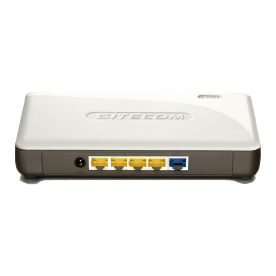
Page 8: Product Layout
Product Layout Port Description Power connector Connect the 12V DC adapter to this port LAN (Yellow) Connect your PC’s or network devices to this port WAN (Blue) Connect your ADSL/Cable modem to this port... - Page 9 Backlabel The backlabel describes the IP address, login details, SSID, security code and WPS button functionality. Button Description Press 0-5 seconds for 2.4 GHz WPS mode WPS BUTTON Press 5-10 seconds for 5 GHz WPS mode Press 10 seconds to reset the router Press 15 Seconds to reset the router to factory defaults.
- Page 10 LED Definition From left to right. Port Description LAN (Blue) Shows the cable is connected. LAN (Blue) Shows the cable is connected. LAN (Blue) Shows the cable is connected. LAN (Blue) Shows the cable is connected. WAN (Blue) Shows the cable is connected. WiFi (White) Shows 5GHz WiFi activity.
-
Page 11: Network + System Requirements
Network + System Requirements To begin using the WLR-5001, make sure you meet the following as minimum requirements: • PC/Notebook. • Operating System – Microsoft Windows XP/2000/VISTA/7 • 1 Free Ethernet port. • WiFi card/USB dongle (802.11 b/g/n) – optional. •... -
Page 12: Setup Lan, Wan
Setup LAN, WAN WAN connection: LAN connection:... -
Page 13: Pc Network Adapter Setup
PC Network Adapter setup Windows XP • Enter [Start Menu] select [Control panel] select [Network]. • Select [Local Area Connection]) icon=>select [properties]... - Page 14 • Select [Internet Protocol (TCP/IP)] =>Click [Properties]. • Select the [General] tab. The WLR-5001 supports a [DHCP] function, please select both [Obtain an IP address automatically] and [Obtain DNS server address automatically].
- Page 15 Windows Vista/Seven • Enter [Start Menu] select [Control panel] select [View network status and tasks] -> select [Manage network connections]. • Select [Local Area Connection]) icon=>select [properties]...
- Page 16 • Select [Internet Protocol Version 4 (TCP/IPv4)] =>Click [Properties]. • Select the [General] tab. The WLR-5001 supports a [DHCP] function, please select both [Obtain an IP address automatically] and [Obtain DNS server address automatically].
-
Page 17: Bring Up The Wlr-5001
Bring up the WLR-5001 Connect the supplied power-adapter to the power inlet port and connect it to a wall outlet. Switch the WLR-5001 on by flipping the switch on the back of the device. The WLR-5001 automatically enters the self-test phase. During self-test phase, the Power LED will be lit continuously to indicate that this product is in normal operation. - Page 18 3. Type user name and password. The default username is admin, the password can be found on the back label on the bottom of your router. 4. Click OK. 5. You will see the home page of the WLR-5001. The System status section allows you to monitor the current status of your router, the UP time, hardware information, serial number as well as firmware version information is displayed here.
- Page 19 LAN settings The LAN tab gives you the opportunity to change the IP settings of the WLR- 5001. Click <Apply> at the bottom of this screen to save any changes. IP address 192.168.0.1. It is the router’s LAN IP address (Your LAN clients default gateway IP address).
- Page 20 IP Address Pool You can select a particular IP address range for your DHCP server to issue IP addresses to your LAN Clients. Note: default IP range is 192.168.0.100 ~ 192.168.0.200. If you want your PC(s) to have a static/fixed IP address, then you’ll have to choose an IP address outside this IP address Pool Domain Name You can specify a Domain Name for your LAN.
- Page 21 Device Status View the Broadband router’s current configuration settings. Device Status displays the configuration settings you’ve configured in the Wizard / Basic Settings / Wireless Settings section.
- Page 22 Internet Status This page displays whether the WAN port is connected to a Cable/DSL connection. It also displays the router’s WAN IP address, Subnet Mask, and ISP Gateway as well as MAC address, the Primary DNS. Press Renew button to renew your WAN IP address.
- Page 23 DHCP Client Status DHCP This page shows all DHCP clients (LAN PCs) currently connected to your network. The table shows the assigned IP address, MAC address and expiration time for each DHCP leased client. Use the Refresh button to update the available information.
- Page 24 WLR-5001 Log View the operation log of the WLR-5001. This page shows the current system log of the Broadband router. It displays any event occurred after system start up. At the bottom of the page, the system log can be saved <Save> to a local file for further processing or the system log can be cleared <Clear>...
- Page 25 WLR-5001 Statistics Shows the counters of packets sent and received on WAN, LAN & WLAN.
-
Page 26: Configuration Wizard
Configuration Wizard Click Internet Settings to configure the router. Here you can choose your internet connection type. Depending on the chosen setting, you may need to enter your user name and password, MAC address or hostname in the following window. After you have entered the correct information, click Apply to save the settings. -
Page 27: Connecting To An External Vpn Service
11.1 Connecting to an external VPN service This section explains how to connect the WLR-5001 to an external VPN service by making use of the supported protocols PPTP, and L2TP+IPSec. If you want to set up the WLR-5001 as a VPN server, you should go to Section 15 “WLR-5001 as a VPN server”. - Page 28 This is a configuration example, where the default configuration for the Internet connection is Dynamic IP Address, but you may also have PPP over Ethernet established as default. 5. At this point you must choose the type of VPN connection you want to set-up. Depending on the VPN service you want to connect to, choose out of: 5a.
- Page 29 Although most of the VPN servers will give you an IP address dynamically, some VPN servers must be configured statically. If you want to configure your IP address dynamically, please skip this step. If you want to configure the VPN statically, click on “Use the following IP address”.
- Page 30 Username and Password. This information must have been provided from your VPN service provided. PPTP Gateway. This value corresponds to either the domain name or public IP address of the VPN server you are trying to connect to. It must have been also provided from your VPN service provider.
- Page 31 configure the VPN statically, click on “Use the following IP address”. Next, fill in the information provided from your VPN service regarding: IP address. This is the IP address that the VPN service has assigned to you. Subnet mask. If you are configuring your IP address statically, your VPN service should have provided you with a subnet mask value along with your IP address.
-
Page 32: Wireless Settings
12 Wireless Settings You can set parameters that are used for the wireless stations to connect to this router for the 2.4Ghz radio or 5Ghz radio. The parameters include Mode, ESSID, Channel Number and Associated Client. Wireless Function Enable or Disable Wireless function here. Click Apply and wait for module to be ready &... - Page 33 Basic Settings Mode Allows you to set the AP to AP, Station, Bridge or WDS mode. Band Allows you to set the AP fixed at 802.11b or 802.11g mode. You can also select B+G mode to allow 802.11b and 802.11g clients at the same time. For the 5GHz mode you can set 802.11a, 802.11n or 802.11a/n mode.
- Page 34 Advanced Settings This tab allows you to set the advanced wireless options. The options included are Authentication Type, Fragment Threshold, RTS Threshold, Beacon Interval, and Preamble Type. You should not change these parameters unless you know what effect the changes will have on the router. Authentication Type There are two authentication types: "Open System"...
- Page 35 Data Rate The “Data Rate” is the rate that this access point uses to transmit data packets. The access point will use the highest possible selected transmission rate to transmit the data packets. N Data Rate The “Data Rate” is the rate that this access point uses to transmit data packets for N compliant wireless nodes.
- Page 36 Security This Access Point provides complete wireless LAN security functions, included are WEP, IEEE 802.11x, IEEE 802.11x with WEP, WPA with pre-shared key and WPA with RADIUS. With these security functions, you can prevent your wireless LAN from illegal access. Please make sure your wireless stations use the same security function, and are setup with the same security key.
- Page 37 When you select 64-bit or 128-bit WEP key, you have to enter WEP keys to encrypt data. You can generate the key by yourself and enter it. You can enter four WEP keys and select one of them as a default key. Then the router can receive any packets encrypted by one of the four keys.
- Page 38 WPA Pre-shared Key Wi-Fi Protected Access (WPA) is an advanced security standard. You can use a pre-shared key to authenticate wireless stations and encrypt data during communication. It uses TKIP or CCMP (AES) to change the encryption key frequently. So the encryption key is not easy to be cracked by hackers. This is the best security available.
- Page 39 This wireless router supports MAC Address Control, which prevents unauthorized clients from accessing your wireless network. Enable wireless access control Enables the wireless access control function Adding an address into the list Enter the "MAC Address" and "Comment" of the wireless station to be added and then click "Add". The wireless station will now be added into the "Current Access Control List"...
- Page 40 Wi-Fi Protected Setup (WPS) is the simplest way to establish a connection between the wireless clients and the wireless router. You don’t have to select the encryption mode and fill in a long encryption passphrase every time when you try to setup a wireless connection. You only need to press a button on both wireless client and wireless router, and WPS will do the rest for you.
- Page 41 Self Pin Code This is the WPS PIN code of the wireless router. You may need this information when connecting to other WPS-enabled wireless devices. SSID This is the network broadcast name (SSID) of the router. Authentication Mode It shows the active authentication mode for the wireless connection.
-
Page 42: Firewall Settings
Firewall Settings The Broadband router provides extensive firewall protection by restricting connection parameters, thus limiting the risk of hacker attacks, and defending against a wide array of common Internet attacks. However, for applications that require unrestricted access to the Internet, you can configure a specific client/server as a Demilitarized Zone (DMZ). - Page 43 If you have a client PC that cannot run an Internet application (e.g. Games) properly from behind the NAT firewall, then you can open up the firewall restrictions to unrestricted two-way Internet access by defining a DMZ Host. The DMZ function allows you to re-direct all packets going to your WAN port IP address to a particular IP address in your LAN.
- Page 44 Denial of Service (DoS) The Broadband router's firewall can block common hacker attacks, including Denial of Service, Ping of Death, Port Scan and Sync Flood. If Internet attacks occur the router can log the events. Ping of Death Protections from Ping of Death attack Discard Ping From WAN The router’s WAN port will not respond to any Ping requests Port Scan Protects the router from Port Scans.
- Page 45 Access You can restrict users from accessing certain Internet applications/services (e.g. Internet websites, email, FTP etc.), Access Control allows users to define the traffic type permitted in your LAN. You can control which PC client can have access to these services. Deny If you select “Deny”...
- Page 46 Add PC Fill in “Client PC MAC Address” and “Comment” of the PC that is allowed to access the Internet, and then click “Add”. If you find any typo before adding it and want to retype again, just click "Reset" and the fields will be cleared.
- Page 47 URL block You can block access to some Web sites from particular PCs by entering a full URL address or just keywords of the Web site. Enable URL Blocking Enable/disable URL Blocking Add URL Keyword Fill in “URL/Keyword” and then click “Add”. You can enter the full URL address or the keyword of the web site you want to block.
-
Page 48: Advanced Settings
14 Advanced Settings Network Address Translation (NAT) allows multiple users at your local site to access the Internet through a single Public IP Address or multiple Public IP Addresses. NAT provides Firewall protection from hacker attacks and has the flexibility to allow you to map Private IP Addresses to Public IP Addresses for key services such as Websites and FTP. - Page 49 Type This is the protocol type to be forwarded. You can choose to forward “TCP” or “UDP” packets only, or select “both” to forward both “TCP” and “UDP” packets. Port Range The range of ports to be forward to the private IP. Comment description of this setting.
- Page 50 Virtual Server Use the Virtual Server function when you want different servers/clients in your LAN to handle different service/Internet application type (e.g. Email, FTP, Web server etc.) from the Internet. Computers use numbers called port numbers to recognize a particular service/Internet application type. The Virtual Server allows you to re-direct a particular service port number (from the Internet/WAN Port) to a particular LAN private IP address and its service port number.
- Page 51 Add Fill in the "Private IP", "Private Port", "Type", “Public Port” and "Comment" of the setting to be added and then click "Add". Then this Virtual Server setting will be added into the "Current Virtual Server Table" below. Reset If you want to remove Virtual Server settings from the "Current Virtual Server Table", select the Virtual Server settings you want to remove in the table and then click "Delete Selected".
- Page 52 Special Applications Some applications require multiple connections, such as Internet games, video Conferencing, Internet telephony and others. In this section you can configure the router to support multiple connections for these types of applications. Enable Trigger Port Enable the Special Application function. Trigger Port This is the out going (Outbound) range of port numbers for this particular application.
- Page 53 Applications selection. Once you have selected an application, select a location (1-10) in the Copy to selection box and then click the Copy to button. This will automatically list the Public Ports required for this popular application in the location (1-10) you specified. Add Fill in the "Trigger Port", "Trigger Type”, “Public Port”, "Public Type", "Public Port"...
- Page 54 UPNP With UPnP, all PCs in you Intranet will discover this router automatically, so you don’t have to configure your PC and it can easily access the Internet through this router. UPnP Feature You can enable or Disable the UPnP feature here. After you enable the UPnP feature, all client systems that support UPnP, like Windows XP, can discover this router automatically and access the Internet through this router without having to configure anything.
- Page 55 QoS can let you classify Internet application traffic by source/destination IP address and port number. You can assign priority for each type of application and reserve bandwidth for it. The packets of applications with higher priority will always go first. Lower priority applications will get bandwidth after higher priority applications get enough bandwidth.
- Page 56 Edit a QoS rule Select the rule you want to edit and click “Edit”, then enter the detail form of the QoS rule. Click “Apply” after editing the form and the rule will be saved. Adjust QoS rule priority You can select the rule and click “Move Up” to make its priority higher.
-
Page 57: Vpn
15 VPN WARNING: This section explains how to set-up the WLR-5001 as a VPN server, so you may connect VPN clients (MacOS, Windows, Android, or any other VPN-ready devices) and establish a Virtual Private Network. If your need is to connect to an external VPN server (i.e. HideMyAss, StrongVPN, SwitchVPN) please refer to Section 11 “Connecting to an external VPN service”. - Page 58 Using the Wizard to Configure the WLR-5001 for a PPTP VPN tunnel. In the Top Menu on the right side, click VPN. In the submenu, click Wizard to add a VPN profile. Click Next to create a VPN profile. In the Name field, enter a name for the PPTP VPN tunnel. This name is for reference purposes.
- Page 59 Click PPTP and click NEXT to continue. Complete the following fields : Enter a name for authentication. User Name Enter a password for authentication. Password Enter any private IP address on a different subnet than the Server IP LAN IP address of the computer connected behind the WLR- 5001.(When WLR-5001 is on default settings, the LAN IP address is 192.168.0.100.
- Page 60 Enable the VPN policy, and then click Apply to save the VPN profile.
- Page 61 Using the Wizard to Configure the WLR-5001 for L2TP over IPSec VPN tunnel. In the Top Menu on the right side, click VPN. In the submenu, click Wizard to add a VPN profile. Click Next to create a VPN profile. In the Name field, enter a name for the L2TP VPN tunnel.
- Page 62 Complete the following fields: Enter a name for authentication. User Name Enter a password for authentication. Password Enter any IP address on a different subnet than the LAN IP Server IP address of the computer connected behind the WLR- 5001.(When WLR-5001 is on default settings, the LAN IP address is 192.168.0.1.
- Page 63 In the following examples it is assumed that the WLR-5001 is placed behind a bridged modem. This means that the Router will receive a public IP address on the WAN side. The WAN/Internet IP address can be found on the Internet status page of the WLR-5001.
- Page 64 Configuring a Microsoft Windows 7 VPN Client Click the Start button and open the Control Panel From the Control Panel, select Network and Internet.(If your control panel view has been set to Icons you can directly go to step 4)
- Page 65 3. From Network and internet, select Network and Sharing center . Under Network and Sharing Center, select Setup a new connection or network.
- Page 66 Click Connect to a workplace, and click Use my internet connection (VPN).
- Page 67 6. Complete the following fields: Enter the WLR-5001 WAN IP address. Internet Address Destination name Enter a name for the VPN client. We recommend to select: Don’t connect now. Just set it up so I can connect later. Click next to continue. 7.
- Page 68 When the following screen appears, click the Close button to close the VPN connection setting. Select Change adapter settings on the left side of the window.
- Page 69 Select the VPN connection you just set, right-click VPN Connection, and select Properties. Go to the Security tab and configure the following settings : Under the Type of VPN, select the Protocol that has been set in the WLR-5001, Point to point tunneling protocol(PPTP) or Layer 2 Tunneling Protocol with IPsec (L2TP-IPSec) .
- Page 70 Go to Network and Sharing Center on the bottom-right of the windows. Under VPN Connection click Connect.
- Page 71 Configuring a Microsoft Windows XP VPN Client Click the Start button and open the Control Panel. From the Control Panel, Click on Network Connections.
- Page 72 Click on Create a network from the left side of the window. Click Next to continue to setup the VPN client.
- Page 73 Select Connect to the network at my workplace and click Next to continue. Select Virtual Private network connection and click Next to continue.
- Page 74 Enter a Company name, this name is only for reference purposes. Enter the Hostname , this should be the WLR-5001 WAN IP address and click Next to continue.
- Page 75 Click Finish to continue, you may choose to add a shortcut for this connection on the Desktop by clicking the checkbox before you click Finish. Click on Properties.
- Page 76 Click on the Security Tab from the top in the window and select Advanced, click Settings to continue.
- Page 77 Configure the following settings: Under Data encryption, select Optional encryption (connect even if no encryption) Check Unencrypted password (PAP) Check Challenge Handshake Authentication Protocol (SPAP) Uncheck Microsoft CHAP (MS-CHAP) Check Microsoft CHAP Version 2 (MS-CHAP v2) Click OK to continue. Click Yes to continue.
- Page 78 14a. If the VPN Type of the tunnel you have set up in the WLR-5001 is L2TP over IPSec You have also entered a Shared key in the WLR-5001(see step 7 of chapter Using the Wizard to Configure the WLR-5001 for L2TP over IPSec for reference).
- Page 79 Configuring a MacOS VPN Client 1. Select System Preferences. On the System preferences panel, Click Network.
- Page 80 Click on the + sign on the bottom left. Select the VPN interface.
- Page 81 Under the VPN Type dropdown, select the option that corresponds to the VPN Type you have configured in the WLR-5001. Enter a name for this profile (this name is for reference purpose only) Complete the following fields: Enter the WAN IP address of the WLR-5001. Server address Enter the name used to log onto the VPN tunnel Account Name...
- Page 82 Complete the following fields: Enter the password that belongs to the Account name which Password you have entered in step 6 of this Guide. If the VPN Type of the VPN tunnel you have set up in the Shared Key WLR-5001 is L2TP over IPSec You have also entered a Shared key in the WLR-5001(see step 7 of chapter Using the Wizard to Configure the WLR-5001 for L2TP over...
- Page 83 Select the checkbox Send all traffic over VPN connection. Click OK to continue. If the VPN tunnel is already connected, click Disconnect and Connect again for the changes made in step 9 to take effect.
- Page 84 Configuring a VPN client on iOS Click Settings on the Springboard. Select General on from the panel of the left side and Click on Network.
- Page 85 Click on VPN. click on Add VPN Configuration…...
- Page 86 Select the VPN Type that corresponds to the VPN Type you have configured in the WLR-5001. Complete the following fields: Enter a name for your VPN connection, this name is for Description reference purposes only. Enter the WLR-5001 WAN IP address Server Enter the name used to log onto the VPN tunnel(this must Account...
- Page 87 Set the Switch to ON to connect to the VPN Network.
- Page 88 Configuring a VPN client on Android Click on Settings. click on More.. from the Settings menu on the upper left. Then Click on VPN.
- Page 89 2. Click on Add VPN Network. Select the VPN Type that corresponds to the VPN Type you have configured in the WLR-5001. Complete the following fields: Enter a name for your VPN connection, this name is for Description reference purposes only. Enter the WLR-5001 WAN IP address Server Enter the name used to log onto the VPN tunnel (this must...
- Page 90 Click on the VPN network you have just created to connect.
- Page 91 Profile Setting This page allows you to Add, Edit and Delete VPN profiles. click here if you wish to manually add a new VPN profile. to edit an existing profile, select one from the list by selecting the Edit corresponding radio button and click ‘Edit’. Click “Apply”...
- Page 92 Add Users to an existing Profile Click on Profile Setting. Select the Profile for which you wish to modify user settings and click on Edit. Then Click on the protocol name you selected to edit.
- Page 93 From here all current users that you have created will be shown. In the Available box existing users are be displayed that do not have access to this VPN Tunnel yet. The Member box displays users that already have access to this VPN Tunnel.
- Page 94 PPTP The Point-to-Point Tunneling Protocol (PPTP) is a method for implementing virtual private networks. PPTP uses a control channel over TCP and a GRE tunnel operating to encapsulate PPP packets. The PPTP specification does not describe encryption or authentication features and relies on the PPP protocol being tunneled to implement security functionality.
- Page 95 L2TP In computer networking, Layer 2 Tunneling Protocol (L2TP) is a tunneling protocol used to support virtual private networks (VPNs). It does not provide any encryption or confidentiality by itself; it relies on an encryption protocol that it passes within the tunnel to provide privacy. General This page allows you to configure the general VPN settings.
- Page 96 IPSec IPSec (Internet Protocol Security) is a protocol suite for securing Internet Protocol (IP) communications by authenticating and encrypting each IP packet of a communication session. IPSec also includes protocols for establishing mutual authentication between agents at the beginning of the session and negotiation of cryptographic keys to be used during the session.
- Page 97 SA (Security Association) A Security Association (SA) is the establishment of shared security attributes between two network entities to support secure communication. An SA may include attributes such as: cryptographic algorithm and mode; traffic encryption key; and parameters for the network data to be passed over the connection.
- Page 98 IPSec (Phase 2) Proposal Protocol Select ESP (Encapsulating Security Payload) or AH (Authentication Header) for traffic through the VPN. • AH (Authentication Header) to provide connectionless integrity and data origin authentication for IP datagrams and to provide protection against replay attacks.
- Page 99 Advanced This page allows you to configure advanced VPN settings. Enabling NAT Traversal allow IPSec traffic from this Nat Traversal endpoint to traverse through the translation process during NAT. The remote VPN endpoint must also support this feature and it must be enabled to function properly over the VPN.
- Page 100 L2TP over IPSec L2TP over IPSec VPNs enable a business to transport data over the Internet, while still maintaining a high level of security to protect data. You can use this type of secure connection for small or remote office clients that need access to the corporate network.
- Page 101 User Setting This page allows you to maintain VPN users. a user Enter the desired name and password, for verification the password has to be entered twice. Click ‘Add’ to add the user to the current VPN user table This button will clear all values from the input boxes. Reset shows all existing VPN users.
- Page 102 Example of configuring IPSec Site to Site architecture In this guide we give an example how to set up a IPSec Site to Site architecture. The values in this example are only to give an impression of how to do the configuration.
- Page 103 Configuring Location B Click on VPN in the top menu then click Wizard in the submenu. Click Next to continue. In the Name field, enter a name for the IPSec VPN tunnel. This name is for reference purposes. Click Next to continue. Click IPSec and click NEXT to continue.
- Page 104 Complete the following fields : Choose the type of Security Gateway you wish to Security Gateway Type use(In this example we use IP address. Enter the WAN IP address of the remote VPN Security Gateway Server( In our example this is the WAN IP address of the WLR-5001 in Location A, 77.193.12.20) Enter an IP address that is on the same Subnet as Remote Address...
- Page 105 Enable the VPN policy, and then click Apply to save the VPN profile. Repeat these steps 1~7 for the other VPN server. Once Both VPN routers have been completely set up. Click on Status in the submenu of the VPN menu and click Connect to establish the IPSec Site to Site connection.
-
Page 106: Toolbox Settings
Your Sitecom device comes with a 6 month free Sitecom cloud security subscription. After you have set up your Sitecom device for internet access, open the webbrowser and enter http://www.sitecomcloudsecurity.com in the address bar. - Page 107 Before you can now activate your subscription you will have to accept the license agreement. After this click the activation button. You will be shown the status of your Sitecom cloud security and the expiration date of your current subscription.
- Page 108 With the protection of unsafe websites activated the Sitecom Cloud Security will always check if a website is safe. If it is not safe it will inform you that is not safe to enter. If you still wish to visit this webpage click on ‘proceed anyway’. Alternatively...
- Page 109 You will be asked for a username and password. These can be found on the backlabel on the bottom of your Sitecom router or modem. If the login succeeded you can click on ‘Settings’ to change your security options.
- Page 110 If you wish to disable to Sitecom cloud security at any time, open the webpage of your Sitecom product and log in with the supplied credentials (these can be found on the back label on the bottom of your Sitecom device).
- Page 111 Password change options You can change the password required to log into the broadband router's system web-based management. Passwords can contain 0 to 12 alphanumeric characters, and are case sensitive. Current Password Fill in the current password to allow changing to a new password.
- Page 112 Time Zone The Time Zone allows your router to base its time on the settings configured here, which will affect functions such as Log entries and Firewall settings. Set Time Zone Select the time zone of the country you are currently in. The router will set its time based on your selection.
- Page 113 Remote Management The remote management function allows you to designate a host in the Internet the ability to configure the Broadband router from a remote site. Enter the designated host IP Address in the Host IP Address field. Host Address This is the IP address of the host in the Internet that will have management/configuration access to the Broadband router from a remote site.
- Page 114 Firmware Upgrade Firmware Upgrade This tool allows you to upgrade the Broadband router’s system firmware. To upgrade the firmware of your Broadband router, you need to download the firmware file to your local hard disk, and enter that file name and path in the appropriate field on this page. You can also use the Browse button to find the firmware file on your PC.
- Page 115 Backup Settings The Backup screen allows you to save (Backup) the router’s current configuration settings. When you save the configuration setting (Backup) you can re-load the saved configuration into the router through the Restore selection. If extreme problems occur you can use the Restore to Factory Defaults selection, this will set all configurations to its original default settings (e.g.
- Page 116 Reset You can reset the router’s system should any problem exist. The reset function essentially re-boots your router’s system.
- Page 117 DDNS DDNS allows you to map the static domain name to a dynamic IP address. You must get an account, password and your static domain name from the DDNS service providers. This router supports DynDNS, TZO and other common DDNS service providers. Enable/Disable Enable or disable the DDNS function of this router Provider Select a DDNS service provider Domain name Fill in your static domain name that uses DDNS...
- Page 118 RaLink SDK 3.1.0.0 Availability of source code Sitecom Europe BV has made available the full source code of the GPL licensed software, including any scripts to control the compilation and installation of the object code on the CD- ROM that’s shipped with this product.
- Page 119 by the GNU Library General Public License instead.) You can apply it to your programs, too. When we speak of free software, we are referring to freedom, not price. Our General Public Licenses are designed to make sure that you have the freedom to distribute copies of free software (and charge for this service if you wish), that you receive source code or can get it if you want it, that you can change the software or use pieces of it in new free programs;...
- Page 120 reasonably considered independent and separate works in themselves, then this License, and its terms, do not apply to those sections when you distribute them as separate works. But when you distribute the same sections as part of a whole which is a work based on the Program, the distribution of the whole must be on the terms of this License, whose permissions for other licensees extend to the entire whole, and thus to each and every part regardless of who wrote it.
- Page 121 under any particular circumstance, the balance of the section is intended to apply and the section as a whole is intended to apply in other circumstances. It is not the purpose of this section to induce you to infringe any patents or other property right claims or to contest validity of any such claims;...
Need help?
Do you have a question about the N600 X5 and is the answer not in the manual?
Questions and answers