
Related Manuals for Nittan CKLD-KPT2


Summary of Contents for Nittan CKLD-KPT2
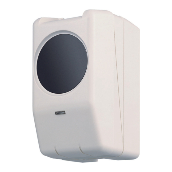
- Page 1 Instruction Manual Beam Type Smoke Detector Thank you for purchasing our product. Please read through the instruction manual before use. Keep this manual in an easily accessible place for future reference.
-
Page 2: Table Of Contents
Table of Contents Handling Instructions ·············································· 3 Names of Parts ····················································· 5 Installation ··························································· 7 Wiring Connection ················································· 9 Adjustment of Light Axis (Transmitter and Receiver) ···· 10 Adjustment of Receiving Light Intensity (Receiver) ······ 11 Sensitivity and Response Time ······························· 14 Sensitivity Test ····················································... -
Page 3: Handling Instructions
Handling Instructions For Your Safety The criteria of the Danger, Warning and Caution markings are as follows. There is a risk of endangering the health or life of the user, or Warning causing a significant damage to the product if the product is mishandled. - Page 4 Handling Instructions Warning 〇Make sure to turn the power off before commencing any wiring work. Otherwise it may cause damage to the equipment. 〇 Avoid installing the product in any location where it can be easily touched by accident. It may cause injury. 〇Ensure to fix the product securely.
-
Page 5: Names Of Parts
Names of Parts Transmitter Upper figure: Cover closed Lower figure: Cover opened Body Lens Cover Cover Power Indicator Base Collimation Hole Collimation Hole Lens Collimation Dial Y Collimation Dial X (Vertical) (Horizontal) Power Indicator Detector Fixing Screw Wiring Hole Lock Tab Wiring Terminal... - Page 6 Names of Parts Receiver Upper figure: Cover closed Lower figure: Cover opened Body Lens Cover Cover Alarm Indicator Base Collimation Hole Collimation Hole Lens Collimation Dial Y Collimation Dial X (Vertical) (Horizontal) Status Switch 調整スイッチ Light Intensity Alarm Indicator Indicator Detector Fixing Wiring Hole Screw...
-
Page 7: Installation
Installation ベース Base ※ベース固定ねじ(なべ小ねじ ※Screws for fixing the base 1※ M4×10)は別途ご用意くだ (Pan-head screw M4x10) さい。 to be prepared separately. 掛け部 Hook Wiring Hole 通線孔 感知器固定ねじ Detector Fixing Screw 1. Pay attention to the vertical direction of the Base and fix it to the wall. - Page 8 Installation Cover holding position 2 Cover holding position 1 Hook Detector Fixing Screw 5. Press the Lock Tab, open and move the body cover upward. The cover can be held at 2 positions to make the installation easier. 6. Fasten the Detector Fixing Screw next to the Wiring Hole. Ensure that the head of the screw is positioned at the specific position of the main body.
-
Page 9: Wiring Connection
5. Ensure to connect the EOL device accompanied with the Remote Station in the line between L and C, and C and K of the Receiver. 6. In case of requirement of taking trouble status of CKLD-KPT2 by compatible control panel through the remote station, make wiring “Lx”... -
Page 10: Adjustment Of Light Axis (Transmitter And Receiver)
Adjustment of Light Axis (Transmitter and Receiver) Collimation Hole Collimation Hole Collimation Axis Collimation Dial X Collimation Dial Y Collimation Dial Two Collimation Dials X and Y are provided to adjust the light axis. Look into one of the Collimation Holes provided above the lens to collimate the opposed unit. -
Page 11: Adjustment Of Receiving Light Intensity (Receiver)
Adjustment of Receiving Light Intensity (Receiver) NORM Lo w O K High FIRE LED flickers while calibration Monitor for Cal L L C C T K K KC SL SC Distance Selection Switch Alarm Indicator Distance Selection SW Alarm Indicator (Flashing during calibration) Light Intensity Adjustment Volume Light Strength Adjustment VR... - Page 12 Adjustment of Receiving Light Intensity (Receiver) 5. Turn and adjust the Light Intensity Adjustment Volume, looking at the Light Intensity Indicator, so that only the green indicator blinks. Light Intensity Indicator Light Intensity Level Too high Orange Green ------ Blinking Slightly high Orange Green...
- Page 13 Adjustment of Receiving Light Intensity (Receiver) 8. After adjusting the Detector, the state of detector can be monitored by using the Remote Station for Beam Detector. For the details of monitoring, refer to the instruction manual of Remote Station for Beam Detector LP04/ LP05. 〇...
-
Page 14: Sensitivity And Response Time
Sensitivity and Response Time The sensitivity of detector (obscuration rate) and response time are shown in the following table. Sensitivity of activation Response Distance between (central value) time Transmitter and Receiver 30 % 4-10 sec 5m to less than 15m 15m to less than 40m 40 % 4-10 sec... -
Page 15: Compensation And Fault Signal
Compensation and Fault Signal 1. The Detector performs compensation process for the slow change of received light intensity which is caused by the contamination of the lens or shifting of light axis. In the monitoring condition, the Detector regularly checks if light intensity received by the Receiver is appropriate. -
Page 16: Test Function
Test Function The remote test function is supported by using Remote Station for Beam Detector (LP04/ LP05) to connect the Detector to P-type control panel. Test is remotely performed by operating the test switch of the Remote Station. Refer to the Operation Instruction Manual of the Remote Station for test method. -
Page 17: Maintenance
Maintenance Fire alarm systems are essential for providing early detection and warning in the event of fire in order to save lives and properties and minimize damage. After installed, periodical maintenance is necessary to keep the facilities in proper condition. Important 〇Note in cleaning Antifog coating is applied to both lenses of the Detector. -
Page 18: Specification
Specification Classification Beam type smoke detector (with test function) Model CKLD-KPT2 Allowable Distance 5m to 100m Sensitivity Distance Sensitivity 5m to less than 15m : 30% 15m to less than 40m 40% : 40m to 100m 65% : Rated Current/ Voltage...
Need help?
Do you have a question about the CKLD-KPT2 and is the answer not in the manual?
Questions and answers