
Related Manuals for Cyfral CC4000


Summary of Contents for Cyfral CC4000
- Page 1 INTERCOM WITH DIGITAL DIALING CC4000 SYSTEM OPERATING, INSTALLATION AND PROGRAMMING MANUAL...
-
Page 2: Table Of Contents
ABLE OF CONTENTS System Features ..............................3 Programming of CC40005 system .......................... 5 Description of programs ............................5 3.1. P01 Panel ................................. 6 3.1.1. Panel type........................................3.1.2. Range of dialed numbers ....................................6 3.1.3. Main electric strike configuration .................................. 7 3.1.4. -
Page 3: System Features
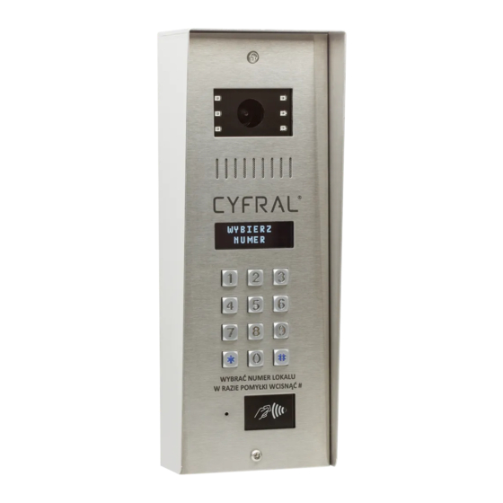
Error codes ................................24 8.3. RS-485 monitor..............................25 1. S YSTEM FEATURES CC4000 It is an intercom system with digital dialing. Main components: • PC-4000 panel It has a housing made of acid-resistant steel, metal backlit mechanical keyboard and an eight-digit alphanumeric display with heating. - Page 4 • DV-4 D ISTRIBUTOR It is used to connect Cyfral videomonitors. • V4 and V7 Videomonitors • Made by Cyfral in 4 and 7 inch versions. • Digital uniphones SMART-D • Programmer GC-2000 For editing control electronics and panel settings using a PC. The appropriate software allows you to archive EEPROM memory on a PC disk.
-
Page 5: Programming Of Cc40005 System
Adjustable separate opening time from the exit button Reverse operation mode of the strike Volume control of the electric strike Gate control Possibility of personal assignment of the entrance to the combination lock/RFID key Individual settings for each subscriber ... -
Page 6: P01 Panel
(At this point it is possible to assign the CC4000 electronics a system number which can be change using the '1', '4', '3', '6', keys). The panel will confirm the correctness of the programming with the following message:... -
Page 7: Main Electric Strike Configuration
3.1.3. In the CC4000 system, the electromagnetic strike is managed by the PC-4000 panel. This subprogram is used to configure the main electric strike LOCK1. Available operation modes: strike released from the first button of the uniphone, proximity key, tenant code... -
Page 8: Factory Settings
3.1.6. Subprogram resetting all panel settings to the default values. Function inactive if a service key fob was used to enter programming. 3.1.7. To enter the programming, you can use the service key fob without knowing the password and serial number of the panel. -
Page 9: Ringtone Type
The volume of the uniphone ring in the range of 1-5. After entering the subprogram there will appear . Using the '1' and '3' keys, set the desired volume and confirm with an asterisk. This function sets the same volume for all physical addresses. -
Page 10: P03 Subscribers
This means that the panel is paired with the control panel with the serial number 600001. The subscriber board in the CC4000 system consists of physical addresses and the subscriber numbers assigned to them. Physical number means uniphone address set by jumpers. The subscriber number means the number to be dialed from the keypad to call the selected uniphone number (physical address). -
Page 11: Deleting A Subscriber Table
3.3.5. Removes all existing subscriber numbers assigned to physical addresses. 3.3.6. Individual settings. Allows you to view the current settings of the selected subscriber and change them if necessary. In the first step, enter the number of the selected subscriber . -
Page 12: Changing A Subscriber's Code
3.4.3. Changes the selected subscriber code. Enter the number of the subscriber whose code you want to change. Next, the code you want to change and the new opening code . Confirm with an asterisk. 3.4.4. Adds a shared opening code for all subscribers. Adding a new code changes the previously saved code. There can only be one shared code in one control panel. -
Page 13: Deleting Of All Subscriber's Electronic Keys
4. S YSTEM CONNECTION The CC4000 system in the basic version for one staircase consists of the CC-4000 control electronics and the PC-4000 digital panel. SUPPLY OF POWER CC-4000 control electronics and PC-4000 panel are supplied with 12-13.8V DC. In order to follow proper working conditions of the system, voltage drops on the power cables must not exceed 1.5V. -
Page 14: Using The Intercom
MASTER PANELS connect to any control electronics in the system. Multiple master panels can be connected to one master terminal in the CC-4000 control panel (video splitter is required in the video version) The DV-4 DISTRIBUTOR is connected to VL, VH, L +, L- terminals. Connect the distributors in parallel to the four-wire bus. -
Page 15: Using Opening Codes
■ Regardless of the time of pressing this button, the bolt is opened for a specified time (5 seconds as standard). ■ All the above times can be changed using the appropriate installation procedures described in this manual. ■ Disconnection takes place when the uniphone is hanged up or the set talk time is exceeded or the key is pressed on the panel keypad. -
Page 16: Connection Diagrams
6. C ONNECTION DIAGRAMS 6.1. Basic video Below is the diagram for connecting the system in the basic video version. In this system, for simplicity, the CC-4000 control electronics should be installed in the PC-4000 panel housing. The connections between the panel and the electronics are made with the shortest possible cables. - Page 17 EXIT BUTTON STRIKE2 MAIN STRIKE CONTROL ELECTRONICS CC-4000 SUPPLY OF POWER 12V/1A POWER SUPPLY FOR UNIPHONES AND MONITORS CC-4000 ELECTRONICS INTEGRATED IN PANEL...
-
Page 18: Basic Audio
6.2. Basic audio Below is the diagram for connecting the system in the basic audio version. In this system, for simplicity, the CC-4000 control electronics should be installed in the PC-4000 panel housing. The connections between the panel and the electronics are made with the shortest possible cables. - Page 19 EXIT BUTTON STRIKE2 MAIN STRIKE CONTROL ELECTRONICS CC-4000 SUPPLY OF POWER 12V/1A POWER SUPPLY UNIPHONES CC-4000 ELECTRONICS INTEGRATED IN PANEL...
-
Page 20: Multi-Input System
There is no limit to the number of parent panels in the CC4000 system. In addition, there is no limit in the number of panels connected to one control electronics. You can, for example, connect four gate panels to one MASTER terminal on the CC-4000 board (in the video version, a vision switch must be inserted). - Page 21 STAIRCASE 1 STAIRCASE 2 EXIT BUTTON EXIT BUTTON STRIKE 2 STRIKE2 MAIN STRIKE MAIN STRIKE CONTROL ELECTRONICS CONTROL ELECTRONICS CC-4000 CC-4000 SUPPLY OF POWER SUPPLY OF POWER 12V/1A POWER SUPPLY 12V/1A POWER SUPPLY SUBSEQUENT STAIRCASES UNIPHONES UNIPHONES AND MONITORS AND MONITORS MAIN INPUT 1 EXIT BUTTON STRIKE 2...
-
Page 22: Installer Functions
In the case of losing a passcode, or lack of knowledge regarding thereof, it is possible to recover it. You can do it in two ways. The first option is to return the equipment to the CYFRAL service, after prior contact. The second method is to read the encrypted code from the keypad of the panel you are interested in. -
Page 23: Searching For Short Circuits
To make the execution of the procedure possible, all connected uniphones must be operational and correctly connected. The idle voltage of the uniphone line should be in the range of 9-10V DC. The ringing volume slider is set to the maximum volume (up). After connecting the uniphone to L + and L- cables, wait 30 seconds for determining the voltage levels. -
Page 24: Diagnostics
8.1. Types of addressing The CC4000 system has three types of addressing between the call panel and the control electronics. Each control electronics has its own unique serial number and the system (building) number assigned by the installer. Depending on the type of the panel that has been set in the subprogram , the panel can communicate with: ... -
Page 25: Rs-485 Monitor
E07 Code in use - The opening code already exists E08 Existing key - The proximity key has already been saved E09 No space for key - Proximity key memory is full E10 No key - Proximity key is not saved E11 Line in use - The uniphone line is in call mode with a subscriber E12 Wrong code - Wrong opening code E13 Invalid administrator code - Invalid passcode or panel serial number has been entered...
Need help?
Do you have a question about the CC4000 and is the answer not in the manual?
Questions and answers