Table of Contents
Advertisement
Quick Links
Advertisement
Table of Contents

Related Manuals for Cyfral PC-4000RV


Summary of Contents for Cyfral PC-4000RV
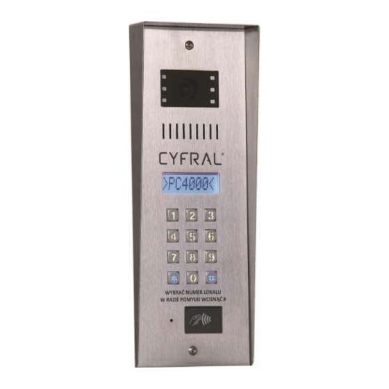
- Page 1 PC-4000RV DIGITAL PANEL OPERATING, INSTALLATION AND PROGRAMMING MANUAL...
- Page 2 introduction ..............................2 General ..............................3 Installation ..............................3 Connection ..............................4 Programming.............................. 6 Camera module ............................7 Miscellaneous ............................8 NTRODUCTION Before installing the device, read the following operating instructions. Installation may only be carried out by a qualified person with the adequate qualifications. This manual applies to the PC-4000 digital panel which is part of the CC4000 system.
- Page 3 ENERAL The front panel is made of acid-proof weather-resistant metal sheet. The casing, however, is made of galvanized steel. Integrated energy-saving RFID UNIQUE 125kHz proximity card reader Fully metal backlit keyboard Large LCD alphanumeric display with backlight ...
- Page 4 ONNECTING OUTPUT BUTTON STRIKE2 MAIN STRIKE For correct operation the panel requires connection to CC-4000 control electronics. A detailed description can be found in the manual for the CC-4000 board. Connection of electro strike and output button on the figure below: The main strike can be a jumper/strike/reversing strike with a maximum current consumption of up to 750mA.
- Page 5 Camera angle adjustment Symmetrical camera connector Panel serial number Connector of the programmer Main connector Connector of the electric strikes...
- Page 6 It should be noted that the main connector and the connector of the electric strikes are of the detachable type. Below is the figure with the connector inserted and removed. The connectors are inserted by pressing-in. ROGRAMMING A complete description of the programming procedure can be found in the manual for the CC4000 system, but the functions related to the PC-4000 panel itself will be described below.
- Page 7 It is not possible to change the serial number with the programmer! If you connect the programmer to the panel that is already part of the entry system installation, first connect the programmer to the panel board, and then the programmer to the USB connector. Otherwise, the board or programmer may be damaged due to possible overvoltages.
- Page 8 The cables that transmit the video signal are connected to the symmetrical connector of the camera. The left 'H' terminal is a non-inverted signal in the phase. The right terminal is inverted in the phase by 180 degrees. The middle terminal is the signal ground of the video. The camera should be connected to appropriate terminals in the CC-4000 control electronics (SLAVE or MASTER, depending on the panel configuration) THER...
Need help?
Do you have a question about the PC-4000RV and is the answer not in the manual?
Questions and answers