Table of Contents
Advertisement
Quick Links
Advertisement
Table of Contents

Related Manuals for DLS FlexxPump 250 DLS


Summary of Contents for DLS FlexxPump 250 DLS
- Page 1 User Manual FlexxPump 250/400 DLS...
-
Page 2: Revision History & Imprint
All rights, including those of photomechanical reproduction, duplication and distribution by means of special processes (e.g. data processing, data carriers and data networks), even in part and/or in extracts, are reserved by DLS Schmiersysteme GmbH. The content and technical specifications are subject to change without notice. -
Page 3: Table Of Contents
Transport and storage Packaging Transport Storage Variants FlexxPump 411 DLS / FlexxPump 211 DLS FlexxPump 412 DLS / FlexxPump 212 DLS FlexxPump 422 DLS / FlexxPump 222 DLS FlexxPump 423 DLS / FlexxPump 223 DLS FlexxPump 424 DLS / FlexxPump 224 DLS... - Page 4 FlexxPump 250/400 DLS User Manual Chapter Content Page Commissioning Operation and settings General information Input and output signals - External control (PLC) Pin assignment - External control (PLC) Input signals - External control (PLC) 8.2.1 Control signal 2 seconds 8.2.2 Control signal 5 seconds 8.2.3...
-
Page 5: General Information About This Manual
General information about this manual This user manual contains all necessary information to use FlexxPump 250/400 in the DLS version safely and as intended. In the event that supplementary sheets are attached to these instructions, the information and data contained in the supplementary sheets are valid and replace the corresponding information in this user manual. -
Page 6: Warning Symbols
FlexxPump 250/400 DLS User Manual Warning symbols The following warning symbols are used in this user manual to alert you to hazards, prohibitions and important information: General warning Electricity hazard Flammable sign material Structure of the safety instructions The safety instructions in this user manual are structured according to the following... -
Page 7: Safety
In order to avoid danger to the user or damage to the machine on which the FlexxPump 250/400 DLS is used, the FlexxPump 250/400 DLS may only be used for its intended purpose (chapter 2.5) and in a technically safe condition. -
Page 8: Usage For The Intended Purpose
Read the user manual and act accordingly. During operation of the FlexxPump 250/400 DLS, a visual inspection of the FlexxPump 400/200 DLS as well as of the lubrication point must be carried out regularly. Any anomalies must be eliminated immediately and the cause rectified. -
Page 9: General Safety Instructions
FlexxPump 250/400 DLS User Manual General safety instructions The following safety instructions are given for the FlexxPump 250/400 DLS: DANGER Damaged or incorrect electrical connections or unauthorized live components lead to serious injuries or even death. § Have all electrical connection work carried out by qualified personnel only. -
Page 10: Description Of Function
(e.g. empty cartridge). By means of various input signals processed by the microelectronics, the FlexxPump 250/400 DLS is controlled to supply the lubrication point with the ideal amount of lubricant. -
Page 11: Nameplate And Designation
User Manual Nameplate and designation The nameplate of the FlexxPump 250/400 DLS is visibly attached to the side of the pump itself. There the CE mark and the serial number of the FlexxPump 250/400 DLS are visible. Refer to chapter 3.1, Fig. 1 for the location of the nameplate and serial number. -
Page 12: Technical Data
FlexxPump 250/400 DLS User Manual Technical data Housing Dimensions without housing 111 x 56,5 x 108 (W x H x D) Dimensions with housing for 250ml cartridge 111 x 165 x 108 (W x H x D) Dimensions with housing for 400ml cartridge 111 x 198,5 x 108 (W x H x D) Weight (without cartridge) appx. -
Page 13: Transport And Storage
Do not throw the FlexxPump 250/400 DLS. Storage Store the FlexxPump 250/400 DLS in its original packaging in a vertical position in a dry, frost-free environment at an ambient temperature of +5°C to +30°C. The maximum storage time in unopened condition is 2 years. -
Page 14: Variants
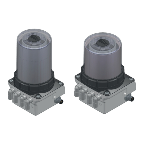
In this case, parts of the system accessories from the manufacturer (e.g. splitters, progressive distributors or lubrication gears) can be connected to the FlexxPump 250/400 DLS in order to extend the number of lubrication points beyond the number of outlets. The FlexxPump 250/400 DLS is available as a variant with one or as a variant with two pump bodies. -
Page 15: Flexxpump 412 Dls/ Flexxpump 212 Dls
Toleranzen / Tolerances: ISO 2768-1 m K Toleranzen / Tolerances: ISO 2768-1 m K FlexxPump 402_ZOF FlexxPump 40 With the FlexxPump 412 DLS or FlexxPump 212 DLS, two outlets are supplied with the Änderung Datum Name Gepr. Schaumstoffteile nach DIN 7715 Teil 5 Klasse P2 Zust. -
Page 16: Flexxpump 422 Dls/ Flexxpump 222 Dls
Toleranzen / Tolerances: ISO 2768-1 m K Toleranzen / Tolerances: ISO 2768-1 m K FlexxPump 402_ZOF FlexxPump 40 With the FlexxPump 422 DLS or FlexxPump 222 DLS, the theoretical two outlets Änderung Datum Name Gepr. Schaumstoffteile nach DIN 7715 Teil 5 Klasse P2 Zust. -
Page 17: Flexxpump 423 Dls/ Flexxpump 223 Dls
Toleranzen / Tolerances: ISO 2768-1 m K Toleranzen / Tolerances: ISO 2768-1 m K FlexxPump 402_ZOF FlexxPump 40 In the FlexxPump 423 DLS or FlexxPump 223 DLS, the theoretical two outlets of the Änderung Datum Name Gepr. Schaumstoffteile nach DIN 7715 Teil 5 Klasse P2 Zust. -
Page 18: Flexxpump 424 Dls / Flexxpump 224 Dls
Toleranzen / Tolerances: ISO 2768-1 m K Toleranzen / Tolerances: ISO 2768-1 m K FlexxPump 402_ZOF FlexxPump 402 With the FlexxPump 424 DLS or FlexxPump 224 DLS, each possible outlet is operated nderung Datum Name Gepr. Schaumstoffteile nach DIN 7715 Teil 5 Klasse P2 Zust. -
Page 19: Mounting
FlexxPump 250/400 DLS User Manual Mounting Preparations Before starting to work, inform yourself in detail about the FlexxPump 250/400 DLS using this user manual; in particular about the general safety instructions (section 2.7). Prepare the installation site carefully. NOTICE Pressurised air can damage the seals of the Flexx- Pump 250/400 DLS and can transport dirt and foreign matter into the FlexxPump 250/400 DLS or the lubricant. - Page 20 Place the full lubricant cartridge on the FlexxPump 250/400 DLS. Turn the lubricant cartridge clockwise onto the FlexxPump 250/400 DLS. The end position is reached after two full rotations when the label of the lubricant cartridge is aligned with the front label of the FlexxPump 250/400 DLS.
- Page 21 4. Assembling the housing on the power unit of the FlexxPump 250/400 DLS. Place the dismantled housing on the FlexxPump 250/400 DLS and press it onto the power unit. Fasten the housing to the power unit by turning the retaining ring clockwise.
- Page 22 FlexxPump 250/400 DLS User Manual DANGER Defective or faulty electrical connections or unauthorized live components can lead to serious injuries or even death. § Have all electrical connection work carried out by qualified personnel only. § Replace damaged cables or plugs immediately.
-
Page 23: Commissioning
5. Hydraulic connection Connect the consumer hydraulically to the FlexxPump 250/400 DLS. If you connect tubes to the FlexxPump 250/400 DLS, make sure that the tubes and connectors are installed tightly, cleanly and correctly. Ideally, use tubes prefilled with the appropriate lubricant! 6. -
Page 24: Operation And Settings General Information
If this is the case, you can operate the FlexxPump 250/400 DLS. If this is not the case, change your PLC program accordingly. To use the FlexxPump 250/400 DLS, it first has to be properly mounted and installed. The installation is very simple and described in detail in chapter 6.2. -
Page 25: Input And Output Signals - External Control (Plc)
PIN 4, and thus enables comprehensive control or, by suitable programming of the PLC, differentiated evaluation of the different statuses. For the integration of the Flexx- Pump 250/400 DLS into an external control, one input and one output must be provided on the control side. -
Page 26: Input Signals - External Control (Plc)
14 seconds. If a high level (+24 V DC) is present outside the tolerances, the FlexxPump 250/400 DLS does not react. If a high level (+24 V DC) is applied to PIN 2 of the electrical interface for longer than 15 seconds, the LCD will display --- and the FlexxPump 250/400 DLS will not react. -
Page 27: Control Signal 2 Seconds
The FlexxPump 250/400 DLS reacts only in a certain operating state to control signals at PIN 2. The operating states are output by the FlexxPump 250/400 DLS via PIN 4 as a high/low level and must be tapped and processed accordingly in the PLC. - Page 28 The FlexxPump 250/400 DLS is properly connected to an external controller via the electrical interface and connected to the power supply. The FlexxPump 250/400 DLS sends a permanent output signal (high level) to PIN 4, which indicates to the external control (PLC) that it is ready for operation. This output signal must be permanently and continuously present for >3 seconds.
-
Page 29: Control Signal 5 Seconds
The FlexxPump 250/400 DLS reacts only in a certain operating state to control signals at PIN 2. The operating states are output by the FlexxPump 250/400 DLS via PIN 4 as a high/low level and must be tapped and processed accordingly in the PLC. - Page 30 The FlexxPump 250/400 DLS is properly connected to an external controller via the electrical interface and connected to the power supply. The FlexxPump 250/400 DLS sends a permanent output signal (high level) to PIN 4, which indicates to the external control (PLC) that it is ready for operation. This output signal must be permanently and continuously present for >3 seconds.
-
Page 31: Control Signal 8 Seconds
The FlexxPump 250/400 DLS reacts only in a certain operating state to control signals at PIN 2. The operating states are output by the FlexxPump 250/400 DLS via PIN 4 as a high/low level and must be tapped and processed accordingly in the PLC. - Page 32 The FlexxPump 250/400 DLS is properly connected to an external controller via the electrical interface and connected to the power supply. The FlexxPump 250/400 DLS sends a permanent output signal (high level) to PIN 4, which indicates to the external control (PLC) that it is ready for operation. This output signal must be permanently and continuously present for >3 seconds.
-
Page 33: Control Signal 12 Seconds
The FlexxPump 250/400 DLS reacts only in a certain operating state to control signals at PIN 2. The operating states are output by the FlexxPump 250/400 DLS via PIN 4 as high/low levels and must be tapped and processed accordingly in the PLC. - Page 34 FlexxPump 250/400 DLS, the motor running time (ML) is 7...17 seconds. At the end of each error-free and successful motor run (ML), the output signal at the FlexxPump 250/400 DLS changes from a low level to a high level for a short pause time P = 0.5 seconds.
-
Page 35: Control Signal 14 Seconds
The control signal 14 seconds is used to acknowledge error messages of errors E2 and E3. It is the only control signal that the FlexxPump 250/400 DLS can process when a low level output signal is sent. Irrespective of the basic possibility of remote acknowled- gement of an error, it is essential to identify and eliminate the cause when an error message is present. - Page 36 The control signal 14 seconds with a signal length of 14 (13.9 ... 14.1) seconds high level can be sent from the external control (PLC) to the FlexxPump 250/400 DLS. The control signal is sent to the FlexxPump 250/400 DLS by the external control (PLC).
-
Page 37: Output Signals - External Control (Plc)
3s and no dispensing process is currently being performed by the FlexxPump 250/400 DLS, there is an error at the FlexxPump 250/400 DLS. The only thing that can be determined by the signalling is that there is an error at the FlexxPump 250/400 DLS. -
Page 38: Empty Level
FlexxPump 250/400 DLS no longer delivers lubricant. This ensures that no air enters the FlexxPump 250/400 DLS or the lubricant lines. The empty state message (error E1) is transmitted to the external control (PLC). For this purpose, a separate, unique output signal is provided, which can be easily and reliably detected by the external control (PLC). - Page 39 (0/+24 V). Z1 indicates the time of removal of the empty cartridge. The output signal of the FlexxPump 250/400 DLS now changes from a 0.5Hz square wave signal to a permanent low signal (0V). Z2 indicates the time for screwing on a new, full cartridge. The output signal of the FlexxPump 250/400 DLS now changes from a permanent low signal (0V) to a permanent high signal (+24V).
-
Page 40: Error Overload
When the maximum permissible pressure is reached during or after a donation, the FlexxPump 250/400 DLS sends a permanent output signal as low level (0 V) to PIN 4 for external control (PLC). The error E2 (overload) must be acknowledged with the control signal 14 seconds (chapter 8.2.5) after elimination of the cause(s). -
Page 41: Error Under- Or Overvoltage
The FlexxPump 250/400 DLS is properly connected to an external controller via the electrical interface and connected to the power supply. If the supply voltage is too low, the FlexxPump 250/400 DLS sends a permanent output signal as low level (0 V) to PIN 4 for external control (PLC). -
Page 42: Critical Error
Important! At least 60 seconds must pass between switching off and on! If this does not correct the E4 error, dismantle the FlexxPump 250/400 DLS and send it back to the manufacturer together with the lubricant cartridge and a description of the error. -
Page 43: Maintenance And Disposal
Check the condition of the lubrication point for correct supply of lubricant. Replace damaged or defective parts immediately to ensure permanent lubrication. Check the filling level of the cartridge on the FlexxPump 250/400 DLS. Check possible error messages on the FlexxPump 250/400 DLS and remedy the causes accordingly. -
Page 44: Cleaning
FlexxPump 250/400 DLS User Manual 9.1.2 Cleaning Clean the FlexxPump 250/400 DLS from dirt using suitable cleaning agents (e.g. absorbent towels, cloths). NOTICE Compressed air can damage the seals of the Flexx- Pump 250/400 DLS as well as transport dirt and foreign bodies into the FlexxPump 250/400 DLS or the lubricant. -
Page 45: Cartridge Change
Cartridge change NOTICE A used lubricant cartridge must not be replaced on the Flexx- Pump 250/400 DLS, as the integrated stroke counter of the FlexxPump 250/400 DLS is automatically reset by the cartridge sensor after a cartridge has been removed. - Page 46 FlexxPump 250/400 DLS User Manual 1. Remove the housing from the power unit of the FlexxPump 250/400 DLS. Separate the housing from the power unit by turning the retaining ring counterclockwise. Make sure that no dirt, water or foreign bodies enters the lubricant inlet.
- Page 47 5. Assembling the housing on the power unit of the FlexxPump 250/400 DLS. Place the dismantled housing on the FlexxPump 250/400 DLS and press it onto the power unit. Fasten the housing to the power unit by turning the retaining ring clockwise.
-
Page 48: Disposal
Disposal When disposing the FlexxPump 250/400 DLS, empty or opened cartridges, observe the relevant national regulations in force. When disposing the FlexxPump 250/400 DLS, observe the relevant safety data sheets and disposal instructions for the individual components. -
Page 49: Released Accessories
The present FlexxPump 250/400 DLS can be considerably extended by the extensive system and accessory program. This may necessitate changes to the PLC program, which controls the FlexxPump 250/400 DLS to ensure reliable and proper operation of the FlexxPump 250/400 DLS together with the hydraulically connected accessories. - Page 50 FlexxPump 250/400 DLS User Manual 134-002-029 Cable M12x1; angled plug; 4-pin; open end; 5 m 134-002-030 Cable M12x1; angled plug; 4-pin; open end; 10m on request Splitter: 2 to 4 outlets multipoint lubrication on request Aluminium progressive distributor: 2 to 10...
-
Page 51: Lubricants
10.1 Tube lengths In principle, the recommendation is to install the FlexxPump 250/400 DLS as close as possible to the consumer (lubrication point). Ideally, this should be done directly at or on the lubrication point. In cases where this is not possible due to the installation space or for reasons of reachability or accessibility, tubes can also be used between the FlexxPump 250/400 DLS and the lubrication point (or distributor). -
Page 52: Appendix
FlexxPump 250/400 DLS User Manual Appendix 11.1 Dimension sheet and installation dimensions 198.5 45.5 33.5 M12x1 revision: 1... -
Page 53: Ec/Eu Declaration Of Conformity
FlexxPump 250/400 DLS User Manual 11.2 EC/EU Declaration of conformity revision: 1... -
Page 54: Flowchart Control Signal 2 Seconds (For Plc)
The adjacent figure illustrates the Start basic program flow chart for the control signal 2 seconds (chapter 8.2.1), which triggers a stroke with 0.15cm³ lubricant on the FlexxPump 250/400 DLS, as well as possible errors. This flow chart PIN 4 nein >3 Sekunden high? - Page 55 DLS Schmiersysteme GmbH Gewerbering 5 D-82140 Olching Tel: +49-(0)8142 650 69-0 Fax: +49-(0)8142 650 69-29 mail@ DLS-Schmiersysteme.de www.DLS-Schmiersysteme.de...
Need help?
Do you have a question about the FlexxPump 250 DLS and is the answer not in the manual?
Questions and answers