Table of Contents
Advertisement
Quick Links
Advertisement
Table of Contents

Related Manuals for DLS FlexxPump 1500


Summary of Contents for DLS FlexxPump 1500
- Page 1 User Guide FlexxPump 1500 / 2000 (24 VDC power supply)
-
Page 2: Table Of Contents
Overview General safety details Use in accordance with guide Extent of warranty General safety information Transport and storage Installation instruction FlexxPump 1500 basics Definitions Control Panel Identification pump units and outlets Grease pouch/bellow How it works Basic operation Start: Visual display Mode: Time control Run –... - Page 3 Connector PIN assignment, connection to FlexxPump 1500 Error messages, faults System Error Master PIN Service: FlexxPump 1500 – readout of the device memory Service: FlexxPump 1500 – replacement of grease pouch Service: FlexxPump 1500 – filling via grease nipple General recommendations...
-
Page 4: Welcome
Welcome Thank you very much for deciding to use our FlexxPump 1500. Make sure that you familiarize yourself with the user guide of this unit and the accessories supplied with this unit. This manual contains important safety information. Preface and General Information The FlexxPump 1500 is an extraordinary compact lubrication pump for oil and grease up to NLGI 2. -
Page 5: Labeling
Gewerbering 5, 82140 Olching, Germany Tel.: +49–8142–65069–0, Fax: +49–8142–65069–29 Email: mail@DLS-schmiersysteme.de, Website: www.DLS-schmiersysteme.de Overview The setup of your FlexxPump 1500 is easy. This user manual will learn you the basic operation and adjustments. Ventilation lock ( with integrated programming) Cover for bellow control panel... -
Page 6: General Safety Details
General safety details Everybody who is involved with the installation, start-up, maintenance and operation of the FlexxPump 1500 must read these instructions carefully! Use in accordance with guide The FlexxPump 1500 is only allowed for industrial use. • The FlexxPump 1500 may only be put into service, if it is integrated or attached to •... -
Page 7: General Safety Information
General safety information Basic information, which must be followed during service, operation and maintenance, are listed as follows. It is absolutely essential that the end user reads the operator’s manual / user guide before installation and start up. In addition to this, it must be permanently available at the site. IMPORTANT Please pay attention, to the safety instructions in this chapter as well as special security cautions that are mentioned throughout the user guide. - Page 8 Prohibited methods of operation Operational security of the FlexxPump 1500 is only guaranteed if it is operated in accordance with the operating instructions. The limit values stated in the technical data must not be exceeded under any circumstances.
-
Page 9: Transport And Storage
Do not throw or expose the FlexxPump 1500 to strong shock loads. Store the FlexxPump 1500 in a cool and dry place to avoid corrosion of the system’s individual parts. Pay attention to the current safety- and accident prevention instructions during the transport. Wear... -
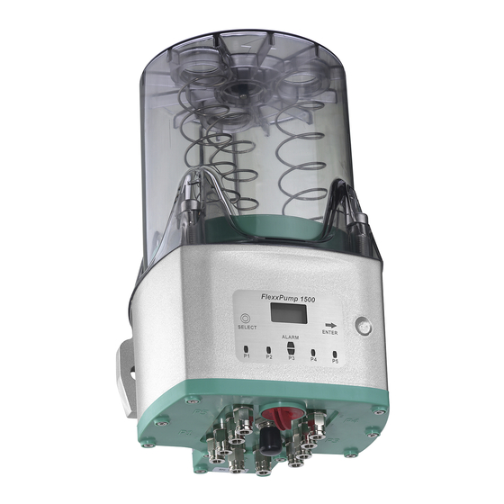
Page 10: Flexxpump 1500 Basics
Definitions Lubrication pump designed for applications with minimal amounts of lubricant: Depending on the configuration FlexxPump 1500 is available with up to 5 pumpunits (P1, P2, P3, P4, P5), each with 2 outlets. 1 pump unit is the housing for 2 piston pumps. 1 pump unit is dispensing equal quantities from both outlets. -
Page 11: Identification Pump Units And Outlets
Identification pump units and outlets Each active pump body (P1, P2, P3, P4, P5) is indicated by a green LED on the control panel. Each active outlet is displayed during a function with a number (1 or 2) on the control panel. -
Page 12: How It Works
How it works After connecting and activating FlexxPump 1500, the piston pump starts to work and pumps the lubricant in small quantities to the outlets. The integrated microprocessor controls the function. Delivery rates and pause time between the lubrication intervals can be individually set. - Page 13 Start: Menu Vers. 20170705...
-
Page 14: Start: Visual Display
Start: Visual display Apply operating voltage Softwareversion: n01 … n99 Operating mode Operating mode Pulse control Next see mode time control or pulse control. Mode: time control SELECT: Change settings - touch the operating pad with the operating / programming key ENTER: Confirmation of all changes - touch the operating pad with the operating / programming key. -
Page 15: Run - Back Pressure Control - Preventive Check On A Lubrication Point
run – back pressure control – preventive check on a lubrication point SELECT: Change settings - touch the operating pad with the operating / programming key ENTER: Confirmation of all changes - touch the operating pad with the operating / programming key. The display flashes 2 times for confirmation. -
Page 16: Pro Program, Menu - Content
Pro program, menu – content Enter PIN Input delivery rates and pause time for every pumpunit ESC: Return to the previous display mode CLr: Clear - delete error messages and delete filling cycles FIL: Filling - de airing the pump, for example – start up, prefilling tubes … Change PIN Change Feedback –... -
Page 17: Input Break Time And Cycle
Input break (pause) time (H: TIME = time between the lubrication intervals in hours) and cycle (C: CYCLE = lubrication quantity) for every pump unit Input H: Time (pause time) = time between the lubrication intervals in hours (1 to 240 h are possible) Display: possible number ->... -
Page 18: Acceptable Design
1500 is accepted consciously. Warning: The ALARM LED flashes on the control panel and the display shows "InF" (for information) for 10s. During this 10s, the operation of FlexxPump 1500 is blocked. Acceptable Design Attention: FlexxPump 1500 is designed for minimum quantity lubrication A higher demand for lubricant at one lubricating point the outlets of different pump units can be combined externally. -
Page 19: Esc - Return To The Previous Display Mode
ESC – Return to the previous display mode SELECT: Change settings - touch the operating pad with the operating / programming key ENTER: Confirmation of all changes - touch the operating pad with the operating / programming key. The display flashes 2 times for confirmation. -
Page 20: Fil - Filling - De Airing The Pump, For Example - Start Up, Prefilling Tubes
If no interaction takes place for a period, the device automatically returns to the previous display mode. Attention: FlexxPump 1500 lubrication pumps must be vented at initial operation. Each pump unit must be vented separately. The operation is completed when lubricant is visible at the outlet. -
Page 21: Change Pin
Change PIN, factory setting PIN: 000 (Master PIN see service) SELECT: Change settings - touch the operating pad with the operating / programming key ENTER: Confirmation of all changes - touch the operating pad with the operating / programming key. The display flashes 2 times for confirmation. -
Page 22: Change Operating Mode: Time Control / Pulse Control
Change operating mode: Time control / pulse control SELECT: Change settings - touch the operating pad with the operating / programming key ENTER: Confirmation of all changes - touch the operating pad with the operating / programming key. The display flashes 2 times for confirmation. -
Page 23: Mode: Pulse Control
Mode: Pulse control SELECT: Change settings - touch the operating pad with the operating / programming key ENTER: Confirmation of all changes - touch the operating pad with the operating / programming key. The display flashes 2 times for confirmation. Timeout: If no interaction takes place for a period, the device automatically returns to the previous display mode. -
Page 24: Enter Pin
Enter PIN, factory setting PIN: 000 (Master PIN see service) SELECT: Change settings - touch the operating pad with the operating / programming key ENTER: Confirmation of all changes - touch the operating pad with the operating / programming key. The display flashes 2 times for confirmation. -
Page 25: Fil - Filling - De Airing The Pump, For Example - Start Up, Prefilling Tubes
If no interaction takes place for a period, the device automatically returns to the previous display mode. Attention: FlexxPump 1500 lubrication pumps must be vented at initial operation. Each pump unit must be vented separately. The operation is completed when lubricant is visible at the outlet. -
Page 26: Change Pin
Change PIN, factory setting PIN: 000 (Master PIN see service) SELECT: Change settings - touch the operating pad with the operating / programming key ENTER: Confirmation of all changes - touch the operating pad with the operating / programming key. The display flashes 2 times for confirmation. -
Page 27: Change Operating Mode: Time Control / Pulse Control
Change operating mode: Time control / pulse control SELECT: Change settings - touch the operating pad with the operating / programming key ENTER: Confirmation of all changes - touch the operating pad with the operating / programming key. The display flashes 2 times for confirmation. -
Page 28: Esc - Return To The Previous Display Mode
ESC – Return to the previous display mode SELECT: Change settings - touch the operating pad with the operating / programming key ENTER: Confirmation of all changes - touch the operating pad with the operating / programming key. The display flashes 2 times for confirmation. - Page 29 Pulse signals to activate pump unit 1 – outlet 1 or outlet 2 Delivery rate per pulse signal: 0,15cm³, indication: 2s, start of delivery rate at outlet 1 or outlet 2, outlets will be served alternately Pulse signals to activate pump unit 1 – outlet 1 and outlet 2 Delivery rate per pulse signal: 0,15cm³, indication: 2s, time between two signals >...
- Page 30 Pulse signals to activate pump unit 3 – outlet 1 and outlet 2 Delivery rate per pulse signal: 0,15cm³, indication: 6s, time between two signals > 20 s, start of delivery rate at outlet 1 or outlet 2, outlets will be served alternately Pulse signals to activate pump unit 4 –...
-
Page 31: Acceptable Design
Acceptable Design Attention: FlexxPump 1500 is designed for minimum quantity lubrication A higher demand for lubricant at one lubricating point the outlets of different pump units can be combined externally. Important remark: unused outlets must remain open to avoid damage to the pump! -
Page 32: Connector Pin Assignment, Connection To Flexxpump 1500
Connector PIN assignment, connection to FlexxPump 1500 Connector PIN assignment M 12 x 1 PIN 1: Input voltage + 24 VDC (-5% to +10%), stabilized operating voltage 24 VDC, color brown PIN 2: Input pulse signal to activate pump unit, color white... - Page 33 E2: not assigned E3: Pump unit works too slowly - Output signal PIN 4 = Low (0 V) Root cause: Low-voltage, pump unit does not work in specified time. This pump unit will stop! Corrective action Eliminate cause, delete error in the program Pro with Clr. Pump will continue to run. Control panel ALARM (red LED) is flashing, Display: Number of pump unit + E3 = 2E3 Example time control (5 activated pump units)
-
Page 34: System Error
Example time control (5 activated pump units) Example pulse control (5 installed pump units) E5: not assigned E6: not assigned E7: Back pressure too high / over-current: output signal PIN 4 = Low (0 V) Root cause: Back pressure was measured 3 x too high. The lubrication point could be clogged, the tube length could be too long or the grease is too stiff or has hardened. -
Page 35: Service: Flexxpump 1500 - Readout Of The Device Memory
Service: FlexxPump 1500 FlexxPump 1500 is designed for minimum quantity lubrication A service for the verification of the performance of FlexxPump 1500 is recommended. Service interval is 50,000 cycles per pump unit. 50,000 cycles correspond 9.000 cm ³ lubricant. Readout of the device memory The number of cycles can be determined by reading the device memory: Touch for 5s the operating pad (ENTER) with the programming key. -
Page 36: Service: Flexxpump 1500 - Replacement Of Grease Pouch
Service: FlexxPump 1500 – replacement of grease pouch Observe the safety instructions Remove locking pin (bottom of the housing) Remove transparent cover: Attention: The internal components of the transparent cover are spring- loaded. Remove the programming key, lock press plate with red locking pin. - Page 37 Remove grease pouch Remove protection from the new cartridge Place the cartridge on the inlet, place the prepared transparent cover Vers. 20170705...
- Page 38 Reinstall the housing while turning the screws with torque 5 Nm, remove the locking pin, reinstall programming Reinstall locking pin: Attention: Function of the pump only after installation of locking pin! 10. The error message is cleared automatically 11. Vent if required (see section FIL) 12.
-
Page 39: Service: Flexxpump 1500 - Filling Via Grease Nipple
- minimum inner diameter is 4mm Ø for tube lenth < 4m - minimum inner diameter is 5mm Ø for tube lenth > 4m and outdoor installation Mounting FlexxPump 1500 2 srews Ø 10mm, for example M10x80 are required for a safe installation of your FlexxPump 1500. Vers. 20170705... -
Page 40: Technical Data Flexxpump 1500
When disposing lubricant the waste disposal instructions of the lubricant Remark ! manufacturer must be observed! Disposal of the FlexxPump 1500: observe the regional valid laws and regulations The empty lubricant bellows /pouches contain lubricant remains! Please dispose with other oil contaminated garbage Acessories Please take note of our complete accessory program in the product catalog.
Need help?
Do you have a question about the FlexxPump 1500 and is the answer not in the manual?
Questions and answers