Advertisement
Quick Links
Advertisement

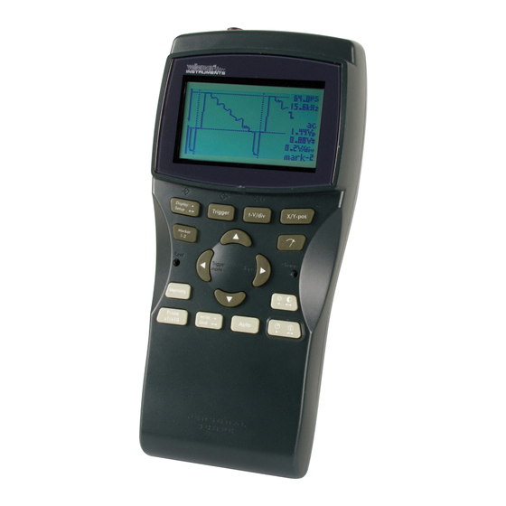
Summary of Contents for Velleman HPS10
- Page 1 © PersonalScope PersonalScope PersonalScope PersonalScope HPS10 Technical Doc 18/11/2002...
-
Page 2: In The Package
HPS10 Technical Doc IN THE PACKAGE: HPS10 unit User Manual PROBE60S OPTIONAL : CASEHPS, hard case BAGHPS, special bag for HPS10 / HPS40 GIB, general instruments bag (soft) PS905, 9Vdc/500mA adaptor © Velleman... - Page 3 HPS10 Technical Doc A division of Velleman Components SAMPLE FOR APPROVAL Model type HPS10 Description Hand Held Personal Scope Sample number: Customer Remarks / modifications to previous sample: Includes: HPS10 unit Manual and documents Safety measuring probe (PROBE60S) Prepared by:...
- Page 4 HPS10 Technical Doc Declaration of Conformity We, Manufacturer Velleman Components Legen Heirweg 33 9890 Gavere Belgium declare that the product HPS10 Personal Scope if used according the instructions included with the unit meet the directives in accordance with 89/336/EEC-EMC Directive...
- Page 5 HPS10 Technical Doc VELLEMAN Instruments Start frequency: 30MHZ HPS10 1 CH Personal Scope End frequency: 1GHz EN55022 Field strenght 30dB Probe correction attenuation © Velleman...
- Page 6 HPS10 Technical Doc VELLEMAN Instruments Start frequency: 30MHZ HPS10 1 CH Personal Scope End frequency: 1GHz EN55022 Field strenght 30dB Probe correction attenuation © Velleman...
- Page 7 HPS10 Technical Doc HPS10 BOM Value/part nr Description + remark Part PHPS5'2 PCB for personal scope 100µ / 25V radial elco (max 12mm high !) C1, C2, C3, C4, C5, C20, C22, C23, C24, C25, C26, C6, C7, C8, C9, C10, C11, C12, C13, C14, C15, C16,...
- Page 8 Graphic LCD LCD1 3mm green led 3mm green NOT MOUNTED: ZD8, R7 Assembly: BHPS10 Enclosure (V-0 ABS) for HPS10, dark green Enclosure HPS10 BNCCHAS SK3 mounted on enclosure bnc connector Battery clip + For mounting in battery compartiment Battery clip -...
- Page 9 BAT54 100µ 100µ 100µ 100µ BZD27-C10V 100µ PM BT2222A AGND AGND Titl e PersonalScope: Power S upply Section Size Number Revision HPS10 Date: 19-Nov-2002 Sheet of File: C:\F iles\M y Documents\In_ont w erp\HPS10\hps10.ddb Drawn B y: Eddy De Cock er...
- Page 10 AG ND DG ND 100µ AG ND PLVA2656A AGND Title PersonalScope: Analog section Size Nu mber Re vision HPS10 Da te: 19-Nov-2 002 She et o f File : C:\Files\MyDocum ents\In_ontwerp\HPS1 0\hps10.dd b Dra wn B y: Eddy De Cock er...
- Page 11 Left Memory DGND LM 311N(8) On/Off Auto ac/dc/gnd Probe x1/x10 Title PersonalScope: Digital S ection DGND Size Number Revision HPS10 PLVA2656A PLVA2656A DGND DGND Date: 19-Nov-2002 Sheet of File: C:\F iles\M y Documents\In_ontwerp\HPS10\hps10.ddb Drawn B y: Eddy De Cock er...
- Page 12 HPS10 Technical Doc © Velleman...
- Page 13 HPS10 Technical Doc Test and calibration Enter the hidden service menu to check the calibration Enter Setup by long pressing Setup Select “Version” with arrow keys and short press setup key to mark it, then leave setup by long press- ing setup key.
- Page 14 HPS10 Technical Doc STEP 1, Offset adjustment. Adjust RV1 until pass is indicated. The trace on the screen must then remain stable. See trimmer location TRIMMER LOCATION: TIP: Pressing Right or Left arrow key, scrolls through the calibration screens ©...
- Page 15 HPS10 Technical Doc Press RIGHT ARROW KEY, STEP 2, Low level transient Connect the (x1) probe to the scope probe test output, If necessary adjust CV1 until pass is displayed See trimmer location Press RIGHT ARROW KEY, STEP 3, High level transient...
- Page 16 HPS10 Technical Doc Press RIGHT ARROW KEY, STEP 4, AD/DC Test Signal should jump up and down. No adjustment, if fail, check cir- cuit round relay RY1, T7.. Press RIGHT ARROW KEY, STEP 5, 50mV/div calibration Connect the (x1) probe with a 0.17Vdc (170mV) supply...
- Page 17 HPS10 Technical Doc Press RIGHT ARROW KEY, STEP 7, 0.2V/div test Connect the (x1) probe with a 0.17Vdc (170mV) supply No adjustment, if fail, check cir- cuit round IC2, IC3, IC4 Press RIGHT ARROW KEY, STEP 8, 0.4V/div test Connect the (x1) probe with a 3.4Vdc supply...
- Page 18 HPS10 Technical Doc Press RIGHT ARROW KEY, STEP 10, 2V/div test Connect the (x1) probe with a 3.4Vdc supply No adjustment, if fail, check circuit round IC2, IC3, IC4 Press RIGHT ARROW KEY, STEP 11, Trace center Adjustment Disconnect the test probe.
-
Page 19: Specifications
SPECIFICATIONS Maximum sample rate 10MS/s for repetitive signals (2MS/s for single shot events) Maximum input amplifier bandwidth 2MHz ( -3dB at 50mV, 1V & 20V /div x1 setting) Input impedance 1Mohm // 20pF (standard oscilloscope probe) Maximum input voltage 100Vpeak (AC + DC), 200Vpeak-peak (AC only) Input coupling DC, AC and GND (GND for auto zero reference) 8 bit + 1bit linearity... - Page 20 A division of Velleman® Components Legen Heirweg 33 9890 Gavere BELGIUM Europe www.vellemaninstruments.com HPS10TD1.0...


Need help?
Do you have a question about the HPS10 and is the answer not in the manual?
Questions and answers