
Related Manuals for Velleman DCM266


Summary of Contents for Velleman DCM266
- Page 1 DCM266 Digital Clamp meter OPERATION MANUAL GEBRUIKERSHANDLEIDING MANUEL D’UTILISATEUR...
-
Page 2: Safety Information
DCM266 Digital Clamp Multimeter 1. Safety Information The meter is completely portable, LCD, 3 1/2 digit clamp with insulation test function (with option 500V insulation tester unit). It has been designed according to IEC-1010 concerning electronic measuring instruments with an overvoltage category (CAT II) and pollution 2 and safety requirements for handheld current clamps for electrical measurement and test. -
Page 3: Maintenance
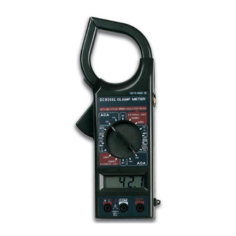
Never use the meter unless the back cover and the battery cover are in place and fastened fully. Do not use abrasives or solvents on the meter, use a damp cloth and mild detergent only. DCM266... - Page 4 AC current, resistance, continuity test and insulation test. Full overload protection, low battery indication and over-range indication are provided. € Transformer jaws ó Trigger ì Data hold switch ö Rotary switch ú LCD display ÷ Input jacks ø Drop-proof wrist strap í Barrier indicator DCM266...
-
Page 5: Input Jacks
During use connect the black test lead to COM jack and connect red test lead to V Ω jack. The red test lead is depended on function selected. The EXT jack is used for accept insulation tester unit EXT banana plugs, when measurement insulation resistance. DCM266... -
Page 6: Measuring Current
7. If the insulation tester unit is not used, the power switch must shift to power OFF position, and the test leads must leave the E, L input connect. That can be increase battery life and prevent electrical shock hazard. DCM266... -
Page 7: Measuring Voltage
( The polarity of the red lead is positive " +") 2. Set the rotary switch at position and connect test leads across two points of the circuit under testing. If continuitiy exists ( i.e., resistance less than about 50Ω ), built-in buzzer will sound. DCM266... -
Page 8: Specifications
±2.0% of rdg ± 5 digits 600A ±2.0% of rdg ± 5 digits Frequency Range : 50Hz to 60Hz Response : Average, Calibrated in rms of sine wave Overload protection : 1200A within 60 seconds. Jaw opening : 2" (5cm) DCM266... - Page 9 Response : Average, calibrated in rms of sine wave 4.5 DC voltage Range Resolution Accuracy 600V ±0.8% of rdg ± 2 digits Input impedance : >9MΩ Over protection : 250Vrms AC for 200mV range 600V peak or 600V rms AC for other ranges DCM266...
-
Page 10: Battery Replacement
Remove the battery cover of case. Replace the exhausted battery with a new one. WARNING Before attempting to open the battery cover, be sure that test leads have been disconnected from measurement circuit to avoid electric shock hazard. DCM266...
Need help?
Do you have a question about the DCM266 and is the answer not in the manual?
Questions and answers