
Related Manuals for Velleman K4304


Summary of Contents for Velleman K4304
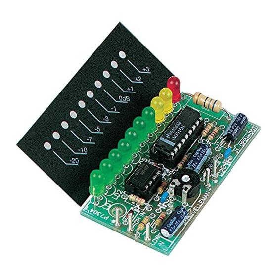
- Page 1 Total solder points: 93 Difficulty level: beginner 1 advanced 10 LED MONO VU METER K4304 ILLUSTRATED ASSEMBLY MANUAL H4304IP-1...
- Page 2 Features & Specifications Features: For instant visualization of audio signal levels. Easy hook up to a LINE level ( LOW input) signal source. For use with mixing panels, amplifiers, CD players, radio’s, ... A special input (HIGH INPUT) is provided, which allows direct connection to a SPEAKER output . DOT or BAR display mode selectable to suit your application.
-
Page 3: Assembly Hints
Assembly hints 1. Assembly (Skipping this can lead to troubles ! ) Ok, so we have your attention. These hints will help you to make this project successful. Read them carefully. 1.1 Make sure you have the right tools: • A good quality soldering iron (25-40W) with a small tip. - Page 4 Assembly hints 1.3 Soldering Hints : 1- Mount the component against the PCB surface and carefully solder the leads 2- Make sure the solder joints are cone-shaped and shiny 3- Trim excess leads as close as possible to the solder joint REMOVE THEM FROM THE TAPE ONE AT A TIME ! AXIAL COMPONENTS ARE TAPED IN THE COR- RECT MOUNTING SEQUENCE !
-
Page 5: Jumper Wires
Construction 1. Jumper wires 2. Diodes. Watch the polarity ! 5. Resistors R... D... CATHODE D1 : 1N4148 : 47K (4 - 7 - 3 - B) D2 : 1N4148 : 47K (4 - 7 - 3 - B) : 330 (3 - 3 - 1 - B) 3. - Page 6 Construction 7. Capacitors. 10. 1W resistor R... C... C1 : 220nF (224) R8 : 68 (6 - 8 - 0 - B ) C2 : 220nF (224) 8. Trim potentiometer 11. IC’s. Watch the polarity ! RV1 : 220K (Sensitivity) 9.
- Page 7 Construction 12. MOUNT THE LEDs (Check the polarity) Remark: Depending on your application, these LED’s can be mounted perpendicular or parallel (see also points 13 and 14): LD1 : green LD3 : green LD5 : green LD7 : green LD9 : yellow LD...
- Page 8 Parallel mounting 13. PARALLEL MOUNTING (optional) (A) Make the holes in the housing or panel (fig.1.0) : Ø3.5 Fig. 1.0 6mm M3 COUNTERSUNK-HEAD BOLT (B) Mount the suitable spacers (fig. 2.0) : 2...3mm FRONTPANEL LOCK WASHER FRONTPANEL 10mm M3 SPACER LOCK WASHER 10mm M3 SPACER Fig.
-
Page 9: Lock Washer
Parallel mounting (C) Mount the PCB onto the spacers (fig 3.0) : 6mm M3 COUNTERSUNK-HEAD BOLT 2...3mm FRONTPANEL LOCK WASHER 10mm M3 SPACER 4mm M3 BOLT 4mm M3 BOLT Fig. 3.0... - Page 10 Perpendicular mounting 14. PERPENDICULAR MOUNTING (optional) (A) Make or search for a suitable bracket : Fig. 4.0 (B) Make the holes in the housing or panel and 10mm M3 COUNTERSUNK-HEAD BOLT mount the bracket (fig. 5.0) : 2...3mm FRONTPANEL FRONTPANEL LOCK WASHER M3 NUT BRACKET...
- Page 11 Perpendicular mounting (C) Mount the PCB with spacers onto the bracket (fig. 6.0) : M3 NUT LOCK WASHER FRONTPANEL 15mm SPACER 20mm M3 BOLT BRACKET 2...3mm FRONTPANEL SOLDER BRACKET SIDE 20mm M3 BOLT M3 NUT Fig. 6.0 15mm SPACER LOCK WASHER...
- Page 12 15. CONNECTION TO A SUITABLE SIGNAL Connecting to a line level output (tuner, preamp, cd player… ) and connecting a power supply from 10 to 15VDC / 110mA max.. HIGH IN TAPE OUT LOW IN K4304 FROM AUDIO AMPLIFIER 1N4007 1000uF/25V 12V/150mA 10...15VDC...
- Page 13 16. CONNECTION TO A SPEAKER OUPUT Connecting to a speaker level output and connecting a power supply from 10 to 15VDC / 110mA max. INPUT (0) HIGH IN SPEAKER OUT LOW IN K4304 FROM POWER AMPLIFIER 1N4007 1000uF/25V 12V/150mA 10...15VDC...
-
Page 14: Speaker Out
HIGH IN SPEAKER OUT LOW IN +12V ANTENNE POWER OUT K4304 CAR RADIO Fig. 9.0 The 12VDC car battery power or car radio antenna output can be used to supply the VU meter. REMARK: Do not connect the unit to a high power car booster or car stereo, this equipment uses isolated ground connection. -
Page 15: Pcb & Diagram
PCB & Diagram 18. PCB LAYOUT 19. DIAGRAM J1 CLOSED = BAR MODE HIGH IN J1 OPEN = DOT MODE 470K SENSITIVITY 68/1W LOW IN 220K +3dB LD10 220n +2dB MODE 1N4148 YELLOW DOT/BAR +1dB YELLOW 1N4148 GREEN -1dB UA741 GREEN LM3916 -3dB... - Page 16 VELLEMAN Components NV Legen Heirweg 33 9890 Gavere Belgium Europe www.velleman.be www.velleman-kit.com Modifications and typographical errors reserved © Velleman Components nv. H4304IP - 2004 - ED1 5 4 1 0 3 2 9 2 8 9 8 9 8...
Need help?
Do you have a question about the K4304 and is the answer not in the manual?
Questions and answers