Advertisement
Assembly Drawing
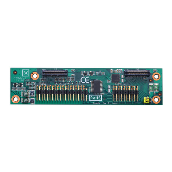
Note: The two 8mm height copper M-F hex stand-offs (P/N: 79380363600E)
which are circled are placed in the AX93292 gift box. Please use them
to ensure AX93292 fully installed on Pico-ITX board.
4
94193292010E
©
Copyright 2017 Axiomtek Co., Ltd.
Version A2 Dec 2017
Printed in Taiwan
AX93292 Quick Installation Guide
Checklist
I/O Board x1
Quick Installation Guide x1
Note: Please contact your local vendors if any damaged or missing items. DO
NOT apply power to the board if there is any damaged component.
Board Layout
Top View
Jumper and Switch Settings
Before applying power to the AX93292, please make sure all of the
jumpers and switch are in factory default positions.
Jumper
Description
Power: Set CN4 pin 11 to +5V level
RS-232 Data: Set CN4 pin 11 to DCD
COM1
(Default)
JP1
Data/Power
Selection
Power: Set CN4 pin 18 to +12V level
RS-232 Data: Set CN4 pin 18 to RI
(Default)
94193292010E
©
Copyright 2017 Axiomtek Co., Ltd.
Version A2 Dec 2017
Printed in Taiwan
Copper M-F hex stand-off x2
Screw x2
Setting
1-3 Close
3-5 Close
2-4 Close
4-6 Close
1
Advertisement
Table of Contents

Related Manuals for AXIOMTEK AX93292


Summary of Contents for AXIOMTEK AX93292
- Page 1 Selection Power: Set CN4 pin 18 to +12V level 2-4 Close which are circled are placed in the AX93292 gift box. Please use them to ensure AX93292 fully installed on Pico-ITX board. RS-232 Data: Set CN4 pin 18 to RI...
- Page 2 USB_Data2- USB_Data3- USB_Data2+ USB_Data3+ +V5S +V5S +V5S +V5S SIO_PSIN# HW_RESET# +V5S HDD_LED 94193292010E 94193292010E © © Copyright 2017 Axiomtek Co., Ltd. Copyright 2017 Axiomtek Co., Ltd. Version A2 Dec 2017 Version A2 Dec 2017 Printed in Taiwan Printed in Taiwan...
Need help?
Do you have a question about the AX93292 and is the answer not in the manual?
Questions and answers