Table of Contents
Advertisement
Quick Links
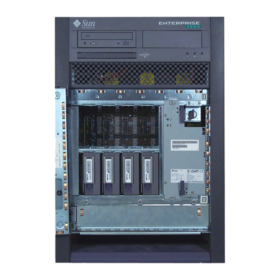
CentreVu Sun Enterprise 3500 Computer Connectivity Diagram
Safety Precautions
For your protection, observe the following safety precautions when setting up your equipment:
•
Follow all cautions, warnings, and instructions marked on the equipment.
•
Never push objects of any kind through openings in the equipment as they may touch
dangerous voltage points or short out components that could result in fire or electric shock.
•
Refer servicing of equipment to qualified personnel.
To protect both yourself and the equipment, observe the following precautions:
Precaution
Item
Problem
Wrist or
ESD
Wear a conductive wrist strap or foot strap when handling printed
foot strap
circuit boards.
Cover panels
System damage
Re-install all cabinet cover panels after performing any service work on
and overheating
the system.
System damage
Make sure all empty board slots have a filler panel installed.
Card cage slot
filler panels
and overheating
Minimum Configuration
The minimum configuration for the computer is:
•
Power/cooling modules (PCMs) or PCM filler panels
•
Fan tray
•
Clock+ board
•
CPU/Memory+ board (with UltraSPARC II CPU modules)
TM
•
Main memory
•
I/O board, either a Graphics+ I/O board or an SBus+ I/O board
•
Fiber Channel-Arbitrated Loop (FC-AL) interface board
•
Board filler panels for any unpopulated board slots
•
Peripheral power supply (PPS) w/AC power sequencer
•
Auxiliary PPS or thermal protection module (TPM)
•
Media tray for removable media, including CD-ROM drive and tape drive
TM
CD ROM
Disk Drive Bays
(mirrored system)
6
4
5
Disk Drive Bays
(non-mirrored system)
0
1
2
Fan Tray
System Precautions
Wear antistatic wrist straps when handling any magnetic storage devices,
CPU/Memory+ boards, or other printed circuit boards.
Enterprise
The
3500 computer has an auto-sensing power supply using nominal input
voltage of 100-240 Volts AC.
Ensure that the voltage and frequency of the power outlet
to be used matches the electrical rating labels on the equipment.
Sun
products are designed to work with single-phase power systems having a grounded
neutral conductor under safety precautions. To reduce the risk of electrical shock, do not
Sun
plug
products into another type of power source. Contact your facilities manager or
qualified electrician if you are unsure what type of power is supplied to your building.
The Enterprise 3500 should be powered by a properly-grounded, non-switched,
dedicated 15-amp circuit.
Each of the following items requires access (by way of a separate power cord):
Enterprise
3500 computer, external peripherals, and monitor.
Warning -
DO NOT make mechanical or electrical modifications to the cabinet.
Sun Microsystems is not responsible for regulatory compliance of modified cabinets.
Tape Drive
FC-AL
Key Switch
7
Interface Board
Auxiliary Peripheral
PPS/AC
Power Supply (PPS)
or Thermal Protection
3
Module
AC Power
Switch
AC Connector
Filler Panel
585-215-877
Comcode 108501883
Issue 2
January 2000
Tools Required
This list represents the minimum of tools and
test equipment you will need:
•
Phillips
Screwdriver,
#2
Phillips
•
Screwdriver,
#1
•
Grounding wrist strap
•
Needlenose pliers
•
Hex driver, 3/32
The slot directly above a
CPU/Memory+ board or
I/O Board must contain
a PCM, because the fans
in the PCM are the only
Power/Cooling
source of cooling air for
Modules (PCM)
the board slot.
Clock+ Board
CPU/Memory+ Board
I/O Board
(Graphics+
or SBus+)
Advertisement
Table of Contents

Related Manuals for Lucent Technologies CentreVu Sun Enterprise 3500


Summary of Contents for Lucent Technologies CentreVu Sun Enterprise 3500
- Page 1 585-215-877 Comcode 108501883 Issue 2 January 2000 CentreVu Sun Enterprise 3500 Computer Connectivity Diagram Safety Precautions System Precautions Tools Required For your protection, observe the following safety precautions when setting up your equipment: Wear antistatic wrist straps when handling any magnetic storage devices, This list represents the minimum of tools and •...
- Page 2 Installing the Fiber Cable Organizer and AC Power Cord Internal Options Use the fiber cable organizer to route the fiber-optic cable to connect the interface board and the I/O board. A 2-meter cable is required when Option Quantity Comments utilizing the internal FC-AL disk drives. The cable organizer can help prevent damage to the fiber-optic cable by ensuring the 1.0 inch minimum bend radius rule is observed.
- Page 3 Wrapping the Fiber Cable on the Organizer Attaching the SCSI Terminator Warning: Plastic dust caps on the ends of the fiber cables must remain 3. Connect that end of the fiber cable into the GBIC module installed on the Enterprise The SCSI connector on the I/O board in slot 1 of any 3500 intact until ready for installation.
- Page 4 Clock+ Board CPU/Memory+ Board SBus+ I/O Board Graphics+ I/O Board SBus 2 (Creator video card installs here) SBus 0 SBus 0 (TurboGX video card installs here) Serial Port B Centerplane (not used) connector GBIC 0 (Top) SCSI (used for (Top) GBIC 1 (Top) Serial Port A...
Need help?
Do you have a question about the CentreVu Sun Enterprise 3500 and is the answer not in the manual?
Questions and answers