Advertisement
Available languages
Available languages
Quick Links
AW 12s-62s, 12a-62a
MONTERINGS- OCH SKÖTSELANVISNING
SE
FÖR VÄRMEFLÄKT VATTEN
VIKTIGT: Läs denna anvisning innan produkten installeras och används.
........................................................................................................................................................................2
INSTALLATION AND MAINTENANCE INSTRUCTION
GB
FOR FAN HEATER UNIT, WATER
IMPORTANT: Read these instructions before the product is installed and used.
........................................................................................................................................................................11
MONTAGE- UND WARTUNGSANLEITUNG
DE
FÜR LUFTERHITZER, WASSER
WICHTIG: Lesen Sie diese Anleitung durch, bevor Sie das Gerät installieren und in
.......................................................................................................................................................................21
Spara anvisningen för framtida bruk.
Save the instructions for future use
Betrieb nehmen.
Verwahren Sie die Montageanleitung fûr den späteren Gebrauch
Art.nr. 172780-02
Advertisement

Subscribe to Our Youtube Channel
Related Manuals for VEAB Heat Tech AW 12s-62s


Summary of Contents for VEAB Heat Tech AW 12s-62s
- Page 1 AW 12s-62s, 12a-62a MONTERINGS- OCH SKÖTSELANVISNING FÖR VÄRMEFLÄKT VATTEN VIKTIGT: Läs denna anvisning innan produkten installeras och används. Spara anvisningen för framtida bruk..................................2 INSTALLATION AND MAINTENANCE INSTRUCTION FOR FAN HEATER UNIT, WATER IMPORTANT: Read these instructions before the product is installed and used.
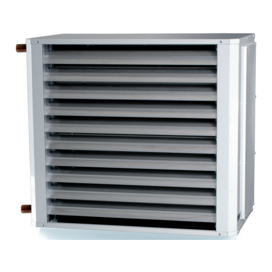
- Page 2 AW 12s-62s, 12a-62a Värmefläkten finns i fyra storlekar AW 12, AW 22, AW 42 och AW 62. Samtliga modeller har som standard tre fläktvarvtal. Värmefläkten är i kappslingsklass IP44 och får installeras i torra, fuktiga och våta rum. Modell AW-a levereras med ventil. Tekniska data på värmefläktarna, se bilaga A.
- Page 3 AW 12s-62s, 12a-62a Montering av filterdel AWK. 1. Lossa de nio skruvarna (AW 62 tolv st) som markerats med pilar enl. bild 1. På AW 22 lossas även de fyra plåtskruvarna. 2. Värmefläkten kan monteras med rören åt vänster eller höger framifrån sett (se bild 12 och 13).
- Page 4 AW 12s-62s, 12a-62a Montering av filter AWPF. 1. Lossa rengöringsluckan på sidan. 2. För in filtret genom öppningen med fjäderdelen mot dig enl. bild 6. Bild 6 Bild 7 3. Placera filtrets fjäderdel på vattenbatteriets plåtkant, tryck filtret mot kopplingsskåpet och mot vattenbatteriet så att filtrets U-profil greppar på...
- Page 5 AW 12s-62s, 12a-62a 3. Värmefläkten kan monteras med rören åt vänster eller höger framifrån sett enl. bild 12 och 13. I lokaler med hög takhöjd bör värmefläkten monteras lågt, dock utan att störa arbetsmiljön. Borrmall för värmefläktarnas väggkonsol med minavstånd till golv, tak respektive vägg, se bilaga C.
- Page 6 AW 12s-62s, 12a-62a 3. Montera värmefläkt med takkonsoler i taket enl. bild 18 och 19. Bild 18 Bild 19 4. Minsta avstånd från värmefläktens bakkant till vägg (pil bild 18) på AW 12 och AW 22 är 200mm. På AW 42 och 62 är minavståndet 270mm.
- Page 7 AW 12s-62s, 12a-62a 9. På AW-a modellerna bör medföljande ventil (tillbehör på AW-s) monteras på det översta röret (utloppet), för att få lägsta temperaturen på ventilen enl. bild 22. Ventilen skall monteras horisontalt med oberoende flödesriktning. Anslutningen till ställdonet riktas rakt upp för att ställdonets IP-klassning ska bibehållas.
- Page 8 AW 12s-62s, 12a-62a Elanslutning AW-s modeller. 1. Installationen skall utföras av behörig installatör. 2. Värmefläkten är utförd för 230V växelström. 3. Elanslutning till nätet skall göras med fast förlagd kabel. Allpolig brytning med brytavstånd på minst 3 mm skall ordnas i den fasta installationen.
- Page 9 AW 12s-62s, 12a-62a 3. Varvtalsomkopplare AWC 12-62 med tre varvtal (bild 29) som väljs manuellt. 1 = lågvarv, 2 = mellanvarv och 3 = högvarv. Skyddsform IP 65. Kan styra max 2 st AW-s värmare. Kopplingsschema se bilaga F. OBS! Om termostat R31 eller SR121/1 används kan max en resp. två AW-s värmare kopplas in.
- Page 10 AW 12s-62s, 12a-62a 6. Till den inbyggda elektroniska termostaten i AW-a, ansluts en rumsgivare med börvärdesinställare TG-R430 ( se bild 31) som har skyddsform IP 30. Rumsgivaren/börvärdesinställaren bör monteras så att den ej påverkas av drag från dörrar och fönster som öppnas, värmefläktens utblåsningsluft eller dyl.
- Page 11 AW 12s-62s, 12a-62a The fan heater is available in four sizes: AW 12, AW 22, AW 42, and AW 62. All models have a three-speed fan as standard. The fan heater is protected to IP44 and may be installed in dry, damp, and wet rooms.
- Page 12 AW 12s-62s, 12a-62a Fitting the AWK filter unit. 1. Unscrew the nine screws (AW 62, twelve screws) indicated by the arrows in photo 1. On the AW 22, you also have to unscrew the four sheet metal screws. The fan heater may be fitted with the pipes facing to the left or to the right, as seen from the front (see photo 12 and 13).
- Page 13 AW 12s-62s, 12a-62a Fitting the AWPF filter unit 1. Open the cleaning door on the side. 2. Insert the filter through the opening with the spring part towards you, acc. to photo 6. Photo 6 Photo 7 3. Place the spring part of the filter on the plate edge of the water coil. Press the filter to the connection box and to the water coil so that the U-section of the filter grips the rear edge of the water coil, acc.
- Page 14 AW 12s-62s, 12a-62a Fitting the AWV wall brackets 1. Unscrew the eight screws indicated by the arrows in photo 10. 2. Fit the brackets as in photo 11. Photo 10 Photo 11 3. The fan heater may be fitted with the pipes facing to the left or to the right, as seen from the front, as in photos 12 and 13.
- Page 15 AW 12s-62s, 12a-62a Fitting the AWT ceiling brackets 1. Unscrew the metal sheet screws on the fan heater, as in photo 16 (four screws each on the AW42 and the AW62). 2. Fit the ceiling brackets as in photo 17.
- Page 16 AW 12s-62s, 12a-62a Water connections for the AW-s and the AW-a ATTENTION! Carefully inspect the whole system for leaks after connecting the water pipes. A leak may cause damage that is expensive to repair. 1. The fan heater must not be connected to hot mains water or steam. The highest temperature and pressure allowed is indicated on the identification plate attached next to the pipes.
- Page 17 AW 12s-62s, 12a-62a 9. The valve that is supplied with the AW-a models (optional for the AW-s), is to be fitted to the upper pipe (outlet), in order to get the lowest temperature (see photo 22). The valve should be installed horizontally with an independent direction of flow.
- Page 18 AW 12s-62s, 12a-62a Electrical connections for AW-s models 1. The work must be done by a qualified electrician. 2. The fan heater is constructed for 230 VAC. 3. The fan heater must be connected to the mains with a permanent cable. A multi-pole breaker with a minimum of 3 mm between the poles must be used for the permanent connection.
- Page 19 AW 12s-62s, 12a-62a 3. Speed regulator AWC 12-62 with three manually chosen speeds (photo 29). 1 = low speed, 2 = medium speed and 3 = high speed. Protected to IP65. Can control a maximum of two AW-s fan heaters. For wiring diagram, see appendix F.
- Page 20 AW 12s-62s, 12a-62a 6. A room temperature sensor and selector, TG-R430 with protection to IP30 (see photo 31) is connected to the built- in electronic thermostat of the AW-a. The room sensor/temperature control should be installed in a place that is not affected by draughts from open doors or windows, the airflow from the heater itself, etc.
- Page 21 AW 12s-62s, 12a-62a Lufterhitzer werden in vier Größen - AW 12, AW 22, AW 42 und AW 62 - geliefert. Alle Größen haben serienmäßig einen 3-Stufen-Ventilator. Der Lufterhitzer darf in trockenen, feuchten und nassen Räumen installiert werden. Schutzart: IP44. Die Modellreihe AW-a wird mit einem Ventil, geliefert.
- Page 22 AW 12s-62s, 12a-62a Montage des Filterteils AWK 1. Die 9 Schrauben (AW 62 12 Schrauben), die im Bild 1 mit Pfeilen gekennzeichnet sind, herausdrehen. Beim AW 22 auch die 4 Blechschrauben herausdrehen. 2. Der Lufterhitzer kann mit den Rohren nach links oder rechts von vorne gesehen montiert werden (siehe Bild 12 und 13).
- Page 23 AW 12s-62s, 12a-62a Montage des Filters AWPF 1. Die Reinigungsöffnung an der Seite öffnen. 2. Das Filter gemäß Bild 6 durch die Öffnung führen, Federseite gegen dir laut Bild 6. Bild 6 Bild 7 3. Der Federteil des Filters auf die Flansche des Wasserregisters platzieren. Das Filter gegen den Anschlusskasten und gegen das Wasserregister drücken, damit die U-Profile des Filters der hinteren Flansche des Wasserregisters greifen,...
- Page 24 AW 12s-62s, 12a-62a Montage der Wandkonsole AWV 1. Die gemäß Bild 10 mit Pfeilen gekennzeichneten 8 Schrauben herausdrehen. 2. Montage der Konsolen gemäß Bild 11. Bild 10 Bild 11 Der Lufterhitzer kann mit den Rohren nach links oder rechts von vorne gesehen, gemäß Bild 12 und 13 montiert werden.
- Page 25 AW 12s-62s, 12a-62a Montage der Deckenkonsole AWT 1. Die Blechschrauben am Lufterhitzer gemäß Bild 16 herausdrehen. (am AW 42 und AW 62 4 Schrauben). 2. Montage der Deckenkonsolen gemäß Bild 17. Bild 16 Bild 17 3. Den Lufterhitzer mit Deckenkonsolen an der Decke montieren (s. Bild 18 und 19).
- Page 26 AW 12s-62s, 12a-62a Wasseranschluss von AW-s und AW-a ACHTUNG! Nach Anschluss der Wasserleitungen das gesamte System genauestens auf Dichtheit kontrollieren. Undichtheiten können schwere Schäden verursachen. 1. Der Lufterhitzer darf nicht an Brauchwasser oder Dampf angeschlossen werden. Die zulässigen Temperatur- und Druckwerte auf dem Typenschild neben den Anschlussstutzen unbedingt beachten.
- Page 27 AW 12s-62s, 12a-62a 9. Bei Modell AW-a muss das beigelieferte Ventil (Zubehör bei AW-s) am obersten Rohrstutzen (Rücklauf ), angebracht werden, um am Ventil eine möglichst niedrige Temperatur zu erhalten (s. Bild 22). Das Ventil ist, unabhängig der Durchflussrichttung, horizontal zu montieren.
- Page 28 AW 12s-62s, 12a-62a Elektrischer Anschluss der AW-s Modelle 1. Die Installation ist von einem zugelassenen Elektro-Installateur durchzuführen. 2. Der Lufterhitzer ist für 230 V Wechselstrom eingerichtet. 3. Der elektrische Anschluss ist mit fest verlegtem Kabel durchzuführen. Die feste Installation soll eine allpolige Abschaltung mit mindestens 3 mm Abschaltabstand haben.
- Page 29 AW 12s-62s, 12a-62a 3. Drehzahlschalter AWC 12-62 mit drei Drehzahlen (Bild 29) ist manuell zu wählen. 1 = Niedrige Drehzahl, 2 = mittlere Drehzahl, 3 = hohe Drehzahl. Schutzart IP 65. Kann maximal zwei AW-s Lufterhitzer regeln. Schaltplan siehe Anlage F.
- Page 30 AW 12s-62s, 12a-62a 6. An den eingebauten elektronischen Thermostaten in AW-s wird ein Raumsensor mit Sollwertgeber TG-R430 (Bild 31) mit der Schutzart IP30 angeschlossen. Der Raumsensor/Sollwertgeber muss so montiert werden, dass er nicht vom Luftzug durch Tür oder Fenster oder von der Ausblasluft des Lufterhitzers o. ä. beeinflusst wird.
- Page 31 AW 12s-62s, 12a-62a Teknisk data AW 12 AW 22 AW 42 AW 62 Spänning 230 V~ 230 V~ 230 V~ 230 V~ Strömförbrukning max 0,36 A 0,58A 0,94 A 2,15 A Teknisk data AW 12 AW 22 AW 42 AW 62 Luftmängd*...
- Page 32 AW 12s-62s, 12a-62a Technical data AW 12 AW 22 AW 42 AW 62 Voltage 230 V~ 230 V~ 230 V~ 230 V~ Technical data AW 12 AW 22 AW 42 AW 62 Power supply max.current 0,36 A 0,58 A 0,94 A...
- Page 33 AW 12s-62s, 12a-62a Technische Daten AW 12 AW 22 AW 42 AW 62 Spannung 230 V~ 230 V~ 230 V~ 230 V~ Stromverbrauch max. 0,36 A 0,58 A 0,94 A 2,15 A Technische Daten AW 12 AW 22 AW 42...
- Page 34 AW 12s-62s, 12a-62a Bilaga B Appendix B Anlage B AWLH AWPF AWLA AWLH AWLA...
- Page 35 AW 12s-62s, 12a-62a Bilaga C Appendix C Anlage C A min. B min. C min. Type AW 12 AW 22 AW 42 AW 62 A min. B min. C min. Type AW 22 AW 42 202,5 202,5 AW 62 185,5...
- Page 36 AW 12s-62s, 12a-62a Kapacitet AW12 Vattentemp. in/ut 90°C/70°C in/ut 80°C/60°C in/ut 60°C/40°C Bilaga D Flöde Tryckfall Flöde Tryckfall Flöde Tryckfall Luftflöde Luft in Luft ut Effekt Luft ut Effekt Luft ut Effekt vatten vatten vatten vatten vatten vatten m³/h °C °C...
- Page 37 AW 12s-62s, 12a-62a Capacity of AW12 Water temp. in/out 90°C/70°C in/out 80°C/60°C in/out 60°C/40°C Appendix D Pressure Pressure Pressure Air flow Flow Flow Flow Air in Air out Output drop. Air out Output drop. Air out Output drop. rate water...
- Page 38 AW 12s-62s, 12a-62a Leistung AW12 Wassertemp. ein/aus 90°C/70°C ein/aus 80°C/60°C ein/aus 60°C/40°C Anlage D Luft- Wasser Druckver. Wasser Druckver. Wasser Druckver. Luft ein Luft aus Leistung Luft aus Leistung Luft aus Leistung strom strom Wasser strom Wasser strom Wasser m³/h °C...
- Page 39 AW 12s-62s, 12a-62a Bilaga E Appendix E Anlage E...
- Page 40 AW 12s-62s, 12a-62a Bilaga F Appendix F Anlage F...
- Page 41 AW 12s-62s, 12a-62a Bilaga G Appendix G Anlage G...
- Page 42 AW 12s-62s, 12a-62a Bilaga H Appendix H Anlage H...
- Page 43 AW 12s-62s, 12a-62a Bilaga I Appendix I Anlage I...
- Page 44 AW 12s-62s, 12a-62a Bilaga K Appendix K Anlage K...
- Page 45 AW 12s-62s, 12a-62a...
- Page 46 AW 12s-62s, 12a-62a...
- Page 47 AW 12s-62s, 12a-62a...
- Page 48 AW 12s-62s, 12a-62a NB: We reserve us from typographical errors and the right to make changes and improvements to the contents of this manual without prior notice. VEAB Heat Tech AB Visitors adress Org.no/F-skatt Postal Cheque Service Phone Box 265 Stattenavägen 50...
Need help?
Do you have a question about the AW 12s-62s and is the answer not in the manual?
Questions and answers