ZKTeco ProFace X Quick Start Manual
Hide thumbs
Also See for ProFace X:
- Quick start manual (11 pages) ,
- User manual (97 pages) ,
- Installation manual (8 pages)

Related Manuals for ZKTeco ProFace X


Summary of Contents for ZKTeco ProFace X
- Page 1 Quick Start Guide ProFace X [TI] Version: 1.0 Due to regular upgrades of systems and products, ZKTeco could not guarantee exact consistency between the actual product and the written information in this manual.
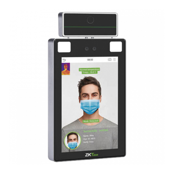
- Page 2 1 Overview Flash Thermal Imaging Temperature Detection Module Near-infrared Flash Camera & Palm Modules Microphone (Optional) 8-inch Touchscreen Tamper Switch Speaker Reset Button +12V Power RS232 RXD1 Power Auxiliary TXD1 interface input 485B RS485 485A Sensor Exit button Wiegand Lock INWD1 Wiegand INWD0...
-
Page 3: Installation Requirements
2 Installation Requirements The installation requirements and indicators associated with temperature detection are given below: Remark Specification Standard Value The recommended operating Indoor, No wind, No direct light, Operating temperature is 25°C(77°F) 16°C to 35°C(60.8°F to 95°F) Environment Distance The recommended distance (between face 30 to 120cm (0.98ft to 3.94ft) is 80cm (2.62ft) -
Page 4: Device Installation
3 Device Installation Installation on the wall ① Attach the mounting template sticker to the wall, and drill holes according to the mounting paper. ② Fix the back plate on the wall using the wall mounting screws. ③ Attach the device to the back plate. ④... - Page 5 3 Device Installation Installation on the barrier gate Please pass the wire through the bracket before installation. ① Drill a hole on the barrier gate, insert the bracket into the hole and fix it with a nut. ② Adjust the angle of the device. ①...
-
Page 6: Standalone Installation
4 Standalone Installation Smoke Alarm detector Door sensor Exit button Reader Lock TCP/IP 5 Door Sensor, Exit Button & Alarm Connection Detector power Smoke detector Door sensor Exit button Alarm Alarm power... -
Page 7: Lock Relay Connection
6 Lock Relay Connection The system supports Normally Opened Lock and Normally Closed Lock. The NO LOCK (normally unlocked when the power is on) is connected with 'NO' and 'COM' terminals, and the NC LOCK (normally locked when the power is on) is connected with 'NC' and 'COM' terminals. Take NC Lock as an example as shown below: 1) Device not sharing power with the lock 2) Device sharing power with the lock... - Page 8 8 Barrier Connection RXD1 TXD1 485B 485A 9 RS485 Connection +12V RXD1 TXD1 485- 485B 485+ 485A 485 reader Note: 485A and 485B can be connected to the Barrier gate or the 485 Reader, separately, but cannot be connected to the gate and reader at the same time.
-
Page 9: Power Connection
10 Power Connection 12V 3A DC Recommended power supply: 12V - 3A To share the power with other devices, use a power supply with higher current ratings. 11 Ethernet Connection Connect the device and the system over an Ethernet cable. An example is shown below: Default IP Address : 192.168.1.201 IP Address... -
Page 10: User Registration
12 User Registration When there is no Super Administrator set in the device, click to enter the menu. After setting the Super Administrator, the system will request for the administrator’s verification before entering the menu. For security purpose, it is recommended to register a Super Administrator at the first time you use the device. - Page 11 192.168.0.31 255.255.255.0 192.168.0.1 XXXX000000000 SpeedFace-H5L This device has been added 192.168.10.214 255.255.255.0 192.168.1.1 XXXX000000000 ProFace X 192.168.4.18 Device Name Icon Type* Door Area* Area Name Add to Level Clear Data in the Device when Adding The current systen communication port is 8088, please make sure the device is set correctly.
- Page 12 Method 3: Register on the phone Once the ZKBioSecurity MTD software is installed, users could enroll their face via browser application on their own mobile phone. 1. Click [Personnel] > [Parameters], input ‘’http://Server address:Port’’ in the QR Code UGL bar. The software will automatically generate a QR code.
-
Page 13: Access Control Settings
13 Ethernet and Cloud Server Settings Click > [Comm.] > [Ethernet] to set the network parameters. If the TCP/IP communication of the device is successful, the icon will be displayed in the upper right corner of the standby interface. Click >... - Page 14 Access Control Options Main Menu Access Control Gate Control Mode Access Control Options Door Lock Delay (s) User Mgt. System User Role COMM. Time Rule setting Door Sensor Delay (s) Holidays Door Sensor Type None Personalize Data Mgt. Access Control Attendance Combined Verification Search...
- Page 15 16 Detection Management Settings Click > [ System ] > [ Detection Management ] to enter the setting interface ❶ You can set the value of High temperature alarm threshold, enable the Temperature over the range; access denied and the Trigger external alarm. The device will send an alarm prompt when the temperature of the detected user exceeds this value, meanwhile the user will be denied access, as shown in the following figure.
- Page 16 Note: 1. The effective distance for temperature detection is within 1.2m. 2. Recommended for indoor use only. 3. The temperature detection data is for reference only, and not for any medical use. 4. Remove the mask to register the face, and wear the mask to recognize the face. The type of mask, face area covered by the mask, and bangs will affect the facial recognition effect.
- Page 17 Welcome, admin 2020-05-28 11:03:07 Real-Time Monitoring Temperature Real-Time Monitoring Total: Statistics Panel Normal Records Abnormal Temperature Temperature Raw Record Personnel Temperature Schedule Abnormal Temperature Name: UnregisterUser Record Departmental body Department: NULL temperature daily statistics report Temperature: 36.57 Parameters Mask: 40.1 C 40.1 C 40.1 C 40.1 C...
- Page 18 17 Palm Enrollment Procedure Note: 1. Place your palm within 30-50cm from the device. 2. Place your palm in the palm detection area, such that the palm is placed parallel to the device. 3. Make sure to keep space between your fingers.
Need help?
Do you have a question about the ProFace X and is the answer not in the manual?
Questions and answers