Advertisement
Quick Links
Quick Start Guide
MINI Imager Series
Step 2 — Connect the System
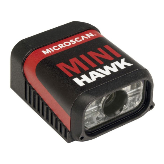
MINI Hawk Xi – Ethernet
• Connect the M12 (power and I/O) end of the imager's cable to the power
supply (2).
• Connect the RJ45 (Ethernet) end of the imager's cable to the host.
• Plug in the power supply to apply power to the imager.
MINI Hawk, Quadrus MINI, Quadrus MINI Velocity – RS-232 /
RS-422 / RS-485
• Connect the imager (1) to the IB-131/IC-332 interface (4) and (3).
• Connect the communication cable (7) to the host, and to the host port
on the IB-131.
• Connect the object detector (6) to the IB-131.
• Connect the power supply (5) to the IB-131.
• Plug in the power supply to apply power to the imager.
Caution:
Be sure that all cables are connected BEFORE applying power
to the system. Always power down BEFORE disconnecting any cables.
Copyright ©2012 Microscan Systems, Inc.
FREE EXTENDED WARRANTY OFFER
www.microscan.com/3year
Standard Warranty: One Year
All Microscan products are backed by a one-year
standard warranty. Full warranty details are online at
www.microscan.com/warranty.
Extended Warranty: Three Years
Register this product online with Microscan to receive
complete extended warranty coverage for three years.
LIMITED TIME OFFER: ACT NOW!
To receive a FREE extended warranty, product MUST
be registered by the end-use installation facility within
four months of the date of manufacture. Online registration
is available at www.microscan.com/3year.
P/N 83-116302 Rev E
Step 3 — Position Imager
• Place the imager and test symbol in a location with as little ambient light
as possible.
• Position the imager at a focal distance between 2" and 6" from the symbol.
• Tip the imager relative to the symbol to avoid glare from specular reflection.
Avoid excessive skew or pitch. Maximum skew is ±30°; maximum pitch is ±30°).
• Symbols can be rotated (tilted) at any angle; however, for best results
symbols should be aligned with the FOV (field of view). In the case of linear
symbols, aligning the bars in the direction of their movement ("ladder"
orientation) will minimize the chances of blurring and No Reads.
Imager / Symbol Positioning
Step 1 — Check Hardware
7
1
2
MINI Hawk, Quadrus MINI,
MINI Hawk Xi
Quadrus MINI Velocity
Hardware Required
Item
Description
MINI Hawk Xi, MINI Hawk, Quadrus MINI,
1
Quadrus MINI Velocity
Power Supply, M12 12-pin Socket, 1.3 m
2
(Screw-On) (MINI Hawk Xi only)
3
IC-332 Adapter
4
IB-131 Interface Box
Power Supply (90-264 VAC, 24VDC,
5
USA/Euro plug)
6
Object Detector
7
Communication Cable
Step 4 — Install ESP
ESP Software can be found on the Microscan Tools Drive that is
packaged with the imager.
1. Follow the prompts to install ESP from the Tools Drive.
2. Click on the ESP icon to run the program.
Note: ESP can also be installed from the Download Center at
www.microscan.com.
Refer to the user's manual for detailed information about using ESP to
configure the imager.
1
3
4
5
6
Part Number
FIS-63X0-XXXXG
97-000003-03
FIS-0001-0035G
99-000018-01
97-100004-15
99-000017-01
61-300026-03
Advertisement

Summary of Contents for Microscan MINI Series
- Page 1 Step 3 — Position Imager Step 4 — Install ESP • Place the imager and test symbol in a location with as little ambient light ESP Software can be found on the Microscan Tools Drive that is MINI Hawk Xi – Ethernet as possible.
- Page 2 For further details, see ESP Help in the dropdown Help menu. Send <@CAL> from a terminal program to begin calibration. You can also start a test with the <C> <Cp> command and end it with the <J> command. Copyright ©2012 Microscan Systems, Inc.


Need help?
Do you have a question about the MINI Series and is the answer not in the manual?
Questions and answers