Table of Contents
Advertisement
Quick Links
Advertisement
Table of Contents

Subscribe to Our Youtube Channel
Related Manuals for Scantool 420GSHT


Summary of Contents for Scantool 420GSHT
- Page 1 METAL BAND SAW 420GSHT INSTRUCTION MANUAL RF-420-110811-R3...
-
Page 2: Table Of Contents
TABLE OF CONTENTS 1. OVERALL ASPECT ..........................2 2.SAFETY RULES FOR ALL TOOLS ......................3 3. SPECIFICATION ........................... 5 4. FEARTURES ............................5 5. TRANSPORTATATION & INSTALLATION: ..................... 6 6. MINIMUM ROOM SPACE FOR MACHINE OPERATION ................7 7. MAKE PROPER TOOTH SELECTION ....................... 7 8. -
Page 3: Overall Aspect
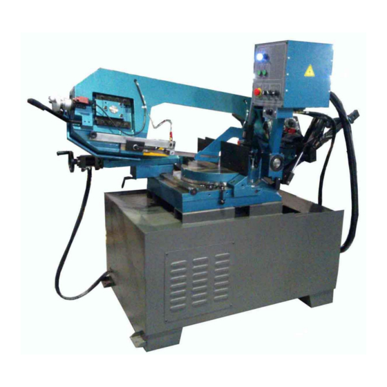
1. OVERALL ASPECT Control Panel Tension Adj. Handle Body Frame Reducer Base Vice Angle Sale Stand... -
Page 4: Safety Rules For All Tools
WARNING: FAILURE TO FOLLOW THESE RULES MAY RESULT IN SERIOUS PERSONAL INJURY As with all machinery there are certain hazards involved with operation and use of the machine. Using the machine with respect and caution will considerably lessen the possibility of personal injury. However, if normal safety precautions are overlooked or ignored, personal injury to the operator may result. - Page 5 (7). AVOID ACCIDENTAL STARTING. Make sure switch is in “OFF” position before plugging in power cord. (8). DIRECTIONOF FEED. Feed work into a blade or cutter against the direction of rotation of the blade or cutter only. (9). ADJUST AND POSITION the blade guide arm before starting the cut. (10).
-
Page 6: Specification
G. NOISE: A weighted sound pressure level : 80 dB. H. SAFETY DEVICE: Interlock switch on cutting area as soon as the cover of cutting area is open, machine will stop at once witch the function of this switch. Do not remove this switch from machine for any reason, and check its function frequently. -
Page 7: Transportatation & Installation
5. TRANSPORTATATION & INSTALLATION: 5-1. Unpacking Transportation to desired location before unpacking, please use-lifting jack. (Fig. B) 2. Transportation after unpacking, please use heavy duty fiber belt to lift up the machine. Fig. B ALLWAYS KEEP PROPER FOOTING & BALANCE WHILE MOVING THIS MACHINE. 5-2. -
Page 8: Minimum Room Space For Machine Operation
6. MINIMUM ROOM SPACE FOR MACHINE OPERATION 1600mm 900mm 2250mm 7. MAKE PROPER TOOTH SELECTION For maximum cutting efficiency and lowest cost per cut, it is important to select the blade with the right number of teeth per inch (TPI) for the material being cut. The material size and shape dictate tooth selection. -
Page 9: Bi-Metal Speeds And Feeds
saw blade must travel to finish the cut. Locate the average width of cut on the chart. Select the tooth Ditch on the ring marked with the tubing and structural shape, which aligns with the average width you are cutting. EXAMPLE: 4"(100mm) outside diameter, 3"(75mm) inside diameter tubing. - Page 10 1026,1513 A36(SHAPES),1040 1042,1541 1044,1045 1060 1095 Ni-Cr-Mo 8615,8620,8622 Alloy Steel 4340,E4340,8630 8640 E9310 Tool Steel A-10 H-11,H-12,H-13 Stainless Steel 410,502 440C 304,324 304L 316,316L TELLTALE CHIPS Chips are the best indicators of correct feed force. Monitor chip information and adjust feed accordingly. Thin or powdered chips –...
-
Page 11: Use Of Main Machine Parts
9. USE OF MAIN MACHINE PARTS 9-1.POWER SYSTEM AND CONTROL PANEL The electrical rating of your band saw is either with 230 or 400 volt-3 phase, magnetic control. Before connecting your machine to an electrical power system, be sure the motor shaft is running in the correct direction. - Page 12 9-2-2. OPERATION OF AUTOMATIC CUTTING AND WORKPIECE SCALE 1, Operation Mode (D). When you select the automatic mode, and push the cutting button (T), the system will run a full cycle of automatic clamp and cutting. 2, Automatic cutting: A1=> Push the automatic cycle button (T) A2=>...
- Page 13 9-4. BOW DOWNWARD WEIGHT ADJUSTMENT In normal situation, when the blade is running, hydraulic valve is on, the bow is going down and cutting and working piece, the bow will maintain 12-15 kgs downward weight to cut the working piece. Different of material of working piece needs different weight of bow to do the cutting.
- Page 14 9-7. BLADE WHEEL POSITION ADJUSTMENT The blade and wheel of RF-420VAA is designed as adjustable. The normal position is same as FIG. (A), the gap between blade FIG. and wheel is around 1 mm maximum. If the gap is less than 1mm, the machine will have huge noise during the operation, the life of blade is shorter.
-
Page 15: Maintaining
9-9. ADJUSTING CUTTING WIDTH First loosen handle screw (A). Move the left blade guide bar to the suitable position. Then tighten handle screw (A). 9-10. PIVOT Occasionally lubricate the pivot using waterproof grease at the fitting (A). 9-11. HOW TO USING CLEAN EQUIPMENT After finished cutting, you can clean the chip by using clean equipment. -
Page 16: Operating And Adjusting Vise
(b) Check electric cord, plugs, switch, bedspring, Cylinder Assembly at least once a year to avoid loosening or wearing. 11. OPERATING AND ADJUSTING VISE Right picture is the Hydraulic Vise set. The hydraulic (B) movement is: turning the handle(A) and make the vise(C) to clamp working object and push the bottom of Hydraulic Vise Clamp. -
Page 17: Trouble Shooting
14. TROUBLE SHOOTING Symptom Possible Cause(s) Corrective Action Machine can not be started 1. Power is not plugged; the power light on 1. Check the motor specification; control panel is not on. connect the power with correct 2. Motor can not be started; power was cut power supply. - Page 18 4. Use coarser tooth blade or brush to remove chips. Motor running too hot 1. Blade tension too high. 1. Reduce tension on blade. 2. Drive belt tension too high. 2. Reduce tension on drive belt. 3. Blade is too coarse for work 3.
-
Page 19: Circuit Diagram
15. CIRCUIT DIAGRAM... -
Page 21: Exploded Diagram
16. EXPLODED DIAGRAM... -
Page 23: Parts List
17. PARTS LIST MODEL NO. 420GSHT CODE PART NO DESCRIPTION SPECIFICATION 131040A 1,00 Rotate the base 123154 2,00 Block HD502 2,00 Hex. Socket Flat Head Scvew M8x15L(8*16) 131043 Regular vice of right 1,00 MHS047 M8x25L 2,00 Hex. Socket Head Screw... - Page 24 19-3 HS444 M10x40L 2,00 Hex. Socker Headless Screw 19-4 HW006 M10X20Xt2 2,00 Washer 19-5 HN006 2,00 Hex. Nut 131097 1,00 Bracket HS046 Hex. Socket Head Screw M8x20L 1,00 HW105 Spring Washer 1,00 HW005 Washer 8.5*18-1.6t (M8) 1,00 HS061 Hex. Socket Head Screw M10x35L 1,00 27-1...
- Page 25 131015A 1,00 Anchor Block 62-1 131014 1,00 Support Lump 62-2 HS261 3,00 Hex. Socket Head Screw M10x35L 62-3 HW106 3,00 Spring Washer 62-4 HS440 2,00 Hex. Headless Screw M10x20L 131071 2,00 Bushing HW105 8,00 Spring Washer HS243 8,00 Hex. Socket Head Screw M8x25L 131072 1,00...
- Page 26 HS286 M12x60L 1,00 Hex. Socket Head Screw HD803 1/8" 2,00 Valve 131019B 1,00 Blade Adjustable (Rear) 101-1 198032AT 1,00 Blade Cover 101-2 HW003 2,00 Washer 101-3 HT019 M5X12L 2,00 Round Head Screw 104-1 131210 1,00 BRUSH BRACKET 104-2 181241C 1,00 Brush 104-3 HS036...
- Page 27 140-1 131178 2,00 Washer 140-2 103214 2,00 flexible plate HT004 M6-1.0P*16L 4,00 Cross Round Head Screw HS558 M5-0.8P*8L 2,00 Cross Round Head Screw 103213B 1,00 Ring 198169M M6*13 2,00 Plum Screw HW004 6.5*13-0.8t (M6) 2,00 Washer 131077A 1,00 Cylinder Assembly 131088 1,00 Spring...
- Page 28 123143 1,00 Positioning seat MHS244 2,00 Hex. Socket Head Screw M8x30L 123141 1,00 Positioning blocks 123146 1,00 Stent Hex. Socket Head Screw MHS332 M5X6L 1,00 Round Head Screw MHT001 M5-0.8Px10L 1,00 Tooth shaft 123144 1,00 wristband 123145 1,00 Spring Washer MHW104 1,00 Hex.
- Page 29 340-7 HW102 1,00 Spring Washer 340-8 HN002 1,00 Hex. Nut 340-9 131218 1,00 Slide 340-10 131219 1,00 Bracket 340-11 HW005 2,00 Washer 340-12 HS219 2,00 Hex. Socket Head Screw M5x16L 340-13 131222 1,00 Bracket 340-14 HW104 3,00 Spring Washer 340-15 HS230 3,00 Hex.
Need help?
Do you have a question about the 420GSHT and is the answer not in the manual?
Questions and answers