
Subscribe to Our Youtube Channel
Related Manuals for CMC ARIZONA VORTEX KIT


Summary of Contents for CMC ARIZONA VORTEX KIT
- Page 1 ARIZONA VORTEX KIT USER MANUAL GENERAL USE (G) NFPA 1983 (2017 ED) 5F04 Find the latest version and translations of the Arizona Vortex User Manual at cmcpro.com...
-
Page 2: Table Of Contents
CARE & USE CERTIFIED CONFIGURATIONS GENERAL WARNINGS VORTEX SPECIFIC WARNINGS VORTEX COMPONENTS VORTEX HARDWARE VORTEX ASSEMBLY BASIC CONFIGURATIONS MULTIPOD SET-UP AND USE EQUAL-LEG TRIPOD EASEL-LEG TRIPOD A-FRAME BIPOD SIDEWAYS A-FRAME GIN POLE MONOPOD INSPECTIONS WARRANTY & SERVICE ARIZONA VORTEX KIT USER MANUAL... -
Page 3: Introduction
INTRODUCTION CARE & USE Congratulations on your purchase of the Arizona Vortex Kit Service Life: The maximum service life of the Vortex metal (Vortex). The Vortex is the most versatile, state of the art and products is not defined; however, the lifespan may be functional multipod available to the rope rigging industries. -
Page 4: Certified Configurations
A-frame section must be at 90 degrees relative to the surface Use either Raptor or Flat Feet Easel leg to A-frame leg distance 10 ft (3 m) Feet are required to be individually hobbled or anchored Easel Tripod (raptor feet) ARIZONA VORTEX KIT USER MANUAL... -
Page 5: General Warnings
• CMC is not responsible for any direct, indirect or accidental consequences or damage resulting from the use or misuse of this product. DIAGRAM LEGEND • The user must stay up to date! Regularly access the CMC website and read the latest advice and user instructions. SYMBOL MEANING •... -
Page 6: Vortex Components
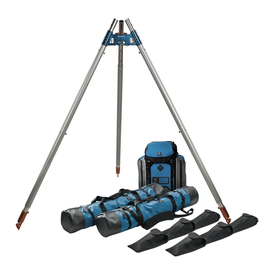
Leg/Foot Pins (17) Flat Feet (3) Raptor Feet (3) Orange Pin Flags (21) Adjustable Hobble Straps (3) 8mm Tether Cord (40ft) User Manual BAG SET: RigTech Pack™ Leg Bags (2) Foot Set Sleeves (2) Pin Storage Bag ARIZONA VORTEX KIT USER MANUAL... -
Page 7: Vortex Hardware
VORTEX HARDWARE OUTER LEG Most of the Vortex hardware Attaches to feet. Can be reversed to components are machined from t into A-Frame & Gin Pole Heads. solid aluminum and incorporate design features that reduce weight INNER LEG and increase strength. Attaches to A-Frame, Gin Pole Head and feet. -
Page 8: Vortex Assembly
The Vortex is designed to enable construc- tion and adjustment of multiple con gura- tions. This diagram shows the assembly of an Easel-Leg Tripod. Outer Legs Outer Legs Inner Leg Inner Leg ARIZONA VORTEX KIT USER MANUAL... - Page 9 ® ARIZONA VORTEX E X P E R T U S E O N L Y USER’S GUIDE A-FRAME HEAD DETAIL VIEW The A-Frame Head can be used individually to construct bipod con gura- tions such as a Classic A-Frame or a Sideways A-Frame. The A-Frame Head has been designed to give the optimal angle between the legs.
- Page 10 Pin the heads together, ensuring the pins lock properly. 1/2” Head Pins with Once connected, the Gin Pole ball-lock fully Head can rotate to change the extended. angle of the Easel-Leg relative to the A-Frame Legs. ARIZONA VORTEX KIT USER MANUAL...
- Page 11 LEGS TO HEADS ASSEMBLY The Vortex utilizes two types of legs: Inner Legs and Outer Legs. Both the Inner and Outer Leg types can be connected to the A-Frame and Gin Pole Head sections. The A-Frame Head section has multiple options for the connecting ball-lock pin.
- Page 12 Two Outer Legs are correctly connected when the alignment stud ts properly into the slot on the other Outer Leg with the ball-lock pin inserted as shown. ARIZONA VORTEX KIT USER MANUAL...
- Page 13 E X P E R T U S E O N L Y LEGS TO FEET ASSEMBLY Both the Raptor Foot and Flat Foot will connect with the Inner Leg and Outer Leg. OUTER Leg INNER Leg Outer Leg shown connected to Raptor Foot.
-
Page 14: Basic Configurations
CONFIGURATION: Sideways A-Frame Easel-Leg Tripod (w/leg-mounted MODE OF USE: winch) Directional Frame MODE OF USE: Anchor Frame CONFIGURATION: Easel-Leg Tripod CONFIGURATION: (w/directional pulley) Gin Pole MODE OF USE: Directional Frame MODE OF USE: Directional Frame ARIZONA VORTEX KIT USER MANUAL... -
Page 15: Multipod Set-Up And Use
Multipod Set-Up and Use RECOMMENDATIONS FOR SETUP CMC highly recommends training for the assembly portion IT IS VITAL THAT THE USER BE ABLE TO DETERMINE THE of the Vortex in a safe environment where all participants DIRECTION AND THE MAGNITUDE OF THE FORCES ACT- can concentrate on the relevant tasks. - Page 16 / pulley system (resul- tant force). • The direction of the applied force will be the bisect of the lines running into and out of the directional pulley /pulley system (resultant force). APPLIED FORCE ARIZONA VORTEX KIT USER MANUAL...
- Page 17 This movement is typically prevented by the applied force (pulley system resul- use of hobbles between the feet. CMC tant) approaches the hobble. recommends that each pair of feet be individually hobbled to obtain maximum security and stability.
- Page 18 Directional Frame will cause a rearward tendency of move- ment. The front legs of the Easel-Leg Tripod will have a tendency to spread apart, while the rear leg will have a tendency to move backwards. APPLIED FORCE ARIZONA VORTEX KIT USER MANUAL...
- Page 19 For Steps 4a & 4b: 3. Bolted to solid surfaces or structure. Adjustable Hobble Straps and Tether Cord are supplied 4. Lashed to objects. with the CMC Arizona Vortex Kit. CMC recommends the following criteria for choosing additional guying material: 1. Lightweight 2.
- Page 20 Applied Force Angle and is the angle formed between the Gin Pole and the guyline. CONFIGURATION: Gin Pole MODE OF USE: Anchor Frame ● Not less than 30° ● Not less than the applied force angle ARIZONA VORTEX KIT USER MANUAL...
- Page 21 CONFIGURATION: Gin Pole Fig. 5b MODE OF USE: Guy Angles on Directional Frame Directional Frame For this Directional Frame, the angle formed between the applied force and the Gin Pole is referred to as the Applied Force Angle. The guy angle directly opposes the Applied Force Angle and is the angle formed between the Gin Pole and the guyline.
- Page 22 Vortex configurations. Each of the following standard configurations has specific attributes, rigging requirements and usage guidelines that should be followed. Other, more complex configurations require advanced rigging skills and expert evaluation prior to being placed in service. ARIZONA VORTEX KIT USER MANUAL...
-
Page 23: Equal-Leg Tripod
CONFIGURATIONS NOTE: GUY LINES OMITTED AND HOBBLE STRAPS FOR CLARITY. EQUAL-LEG TRIPOD The Equal-Leg Tripod shown is a Directional Frame, as the frame supports a pulley system and the haul line is CONFIGURATION: Tripod not terminated onto the frame. The use of indepen- dent hobbles alone is normally considered accept- MODE OF USE: Directional Frame... -
Page 24: Easel-Leg Tripod
Care must be taken to ensure the load is kept well within the triangle. Keep the Applied Force within the footprint of Easel-Leg Frame. CONFIGURATION: Easel-Leg Tripod (with leg-mounted winch) MODE OF USE: Anchor Frame VIEWS TOP VIEW SIDE VIEW ARIZONA VORTEX KIT USER MANUAL... - Page 25 CONFIGURATIONS EASEL-LEG TRIPOD (with Leg-Mounted Winch) The Easel-Leg Tripod shown is an Anchor Frame as the rope that supports the load is anchored to the frame via a leg-mounted winch. The use of hobbles alone is not adequate to secure this configuration.
- Page 26 Avoid cantilevering the head over the edge if possible. If the head is cantilevered, for example when lifting an untendered load, secure the head with one or more guy lines. CONFIGURATION: Easel-Leg Tripod MODE OF USE: Directional Frame APPLIED FORCE VIEWS TOP VIEW SIDE VIEW ARIZONA VORTEX KIT USER MANUAL...
-
Page 27: A-Frame Bipod
CONFIGURATIONS A-FRAME BIPOD The A-Frame configuration shown is a Directional Frame as the rope supporting the load is directed through a pulley on the head and is not anchored to the frame. The example shown would require a combination of hobbles and Raptor Feet inserted into crevices and guys to provide security and stability. -
Page 28: Sideways A-Frame
APPLIED FORCE CONFIGURATION: Sideways A-Frame MODE OF USE: Directional Frame Keep the Applied Force centered within the footprint/Frame Plane of the Bipod. VIEWS TOP VIEW SIDE VIEW ARIZONA VORTEX KIT USER MANUAL... -
Page 29: Gin Pole Monopod
CONFIGURATIONS GIN POLE MONOPOD The Gin Pole configuration shown is a Directional Frame as the rope supporting the load is directed through a pulley on the head and is not anchored to the frame. The example shown would require a combination of hobbles, Raptor feet inserted into a crevice and guys to provide security and stability. -
Page 30: Inspections
• Misalignment of joining parts person that is authorized to do so. Contact CMC if you have any doubts or concerns. • Legs that do not easily fit together and adjust... -
Page 31: Warranty & Service
WARRANTY INSPECTION RECORD If your CMC product has a defect due to workmanship or materials, please contact CMC Customer Support for warran- DOCUMENTATION ty information and service at info@cmcpro.com. Model Serial # CMC’s warranty does not cover damages caused by improper... - Page 32 CMC Rescue, Inc. 6740 Cortona Drive Goleta, CA 93117, USA 805-562-9120 / 800-235-5741 cmcpro.com ISO 9001 Certified ©2020 CMC Rescue, Inc. All rights reserved CMC and are registered marks of CMC Rescue Inc. Control No. 910001_Rev00...
Need help?
Do you have a question about the ARIZONA VORTEX KIT and is the answer not in the manual?
Questions and answers