Advertisement
Quick Links
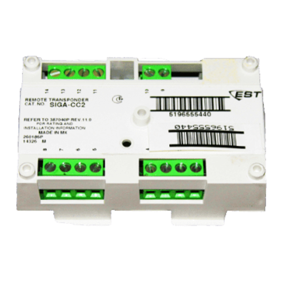
SIGA-CC2 Dual Input Signal Module
Installation Sheet
Description
The SIGA-CC2 Dual Input Signal Module is an addressable
device that connects one of two risers to a Class B supervised
output circuit.
When activated, the module connects the output circuit to the
Riser 1 or Riser 2 input. The input can be either 24 VDC (to
operate polarized audible and visible signal notification
appliances), or 25 or 70 VRMS (to operate audio evacuation
speakers). Typically, the Riser 1 input connects to the ALERT
channel and the Riser 2 input connects to the EVAC channel.
The module does not provide signal synchronization. To meet
UL 864 requirements for horn and strobe signal
synchronization, you must install a Genesis Signal Master
module. This module does not provide supervision of the riser;
the fire alarm panel provides this function.
The SIGA-CC2 module requires two addresses on the
signaling line circuit (SLC). Addresses are assigned
electronically. There are no address switches.
Diagnostic LEDs provide visible indication of the state of the
module through the cover plate:
•
Normal: Green LED flashes
•
Alarm/active: Red LED flashes
© 2017 United Technologies Corporation
Personality codes
Use the personality codes described below to configure the
SIGA-CC2 module. See Table 1 for listing information.
Table 1: Personality codes
Code
Description
7
Riser selector -
supervised output
(Class B)
Personality code
7: Riser selector - supervised output
(Class B). Configures the SIGA-CC2 module as a
one - or two - input, signal power (24 VDC) or audio evacuation
(25 or 70 VRMS) riser selector. The output circuit is monitored
for open or shorted wiring. If a short exists, the control panel
inhibits the activation of the signal circuit, so the riser is not
connected to the wiring fault.
Installation
Install this device in accordance with applicable national and
local codes, ordinances, and regulations.
Notes
•
The module is shipped from the factory as an assembled
unit; it contains no user-serviceable parts and should not
be disassembled.
•
This module does not operate without electrical power. As
fires frequently cause power interruption, discuss further
safeguards with the local fire protection specialist.
To install the module:
1.
Write the address assigned to the module on the label
provided, and then apply the label to the module. Remove
the serial number label from the module, and then attach it
to the project documentation.
Wire in accordance with "Wiring" on page 2.
2.
3.
Using the self-tapping screw provided, attach the wall
plate to the module. See Figure 1.
4.
Using the four machine screws, attach the wall plate and
module to the electrical box.
1 / 5
UL 864
CAN/ULC-
S527
P/N 387040P-EN • REV 013 • ISS 20SEP17
EN 54-18
Advertisement

Related Manuals for Edwards SIGA-CC2


Summary of Contents for Edwards SIGA-CC2
- Page 1 Description connected to the wiring fault. The SIGA-CC2 Dual Input Signal Module is an addressable device that connects one of two risers to a Class B supervised Installation output circuit.
- Page 2 Each terminal on the module is limited to a single conductor. • Test resistors are supplied with the SIGA-CC2 to prevent trouble signals on unused circuits during installation. When connecting field wires, remove the test resistors and install a UL/ULC Listed 47 kΩEOLR at the end of the circuit.
- Page 3 Figure 3: Wiring diagram for NAC (1)(2)(3)(4) (11) (12) (10) (1) Signal polarity is shown when the circuit is in supervisory state. (4) If using a G1-P Genesis series horn while connected to a Polarity reverses when the circuit is active. compatible fire alarm control panel, a CDR-3 Bell Coder must (2) Supervised.
- Page 4 Figure 4: Wiring diagram for audio (1)(2)(3)(4) (11) (12) (10) (1) Signal polarity is shown when the circuit is in supervisory state. (4) Unshielded twisted pair. (5) 47 kΩ EOLR (P/N EOL-47). Polarity reverses when the circuit is active. (2) Supervised. (6) Signaling line circuit (SLC) to next device.
-
Page 5: Specifications
Specifications Regulatory information Operating voltage range 15.20 to 19.95 VDC FCC compliance This device complies with part 15 of the FCC Rules. Operation is subject to the following two Current conditions: (1) This device may not cause Standby 310 µA harmful interference, and (2) this device must Activated 135 µA...
Need help?
Do you have a question about the SIGA-CC2 and is the answer not in the manual?
Questions and answers