Table of Contents
Advertisement
Quick Links
Advertisement
Table of Contents

Related Manuals for TSUNESS TSOL-A3.0K-H


Summary of Contents for TSUNESS TSOL-A3.0K-H
- Page 1 TSOL-A3.0K-H TSOL-A3.6K-H TSOL-A4.0K-H TSOL-A4.6K-H TSOL-A5.0K-H TSOL-A6.0K-H...
-
Page 3: Table Of Contents
Content 1 Notes on this Manual............................1 1.1 Scope of Validity ............................1 1.2 Target Group ..............................1 1.3 Symbols Used .............................1 2 Safety ..................................2 2.1 Important Safety Instructions .........................2 2.2 Explanation of Symbols ..........................5 2.3 CE Directives...............................6 3 Introduction..............................7 3.1 Basic features.............................7 3.2 Work Modes............................ - Page 4 8.2 Routine maintenance ..........................45 9 Decommissioning ............................... 46 9.1 Remove the Inverter ..........................46 9.2 Packaging ..............................46 9.3 Storage and Transportation ......................... 46 10 Warranty Card..............................47...
-
Page 5: Notes On This Manual
1 Notes on this Manual 1.1 Scope of Validity This manual is an integral part of TSOL Inverter, it describes the assembly, installation, commissioning, maintenance and failure of the product. Please read it carefully before operating. TSOL-A3.0K-H TSOL-A3.6K-H TSOL-A4.0K-H TSOL-A4.6K-H TSOL-A5.0K-H TSOL-A6.0K-H... -
Page 6: Safety
2 Safety 2.1 Important Safety Instructions Danger! Danger to life due to high voltages in the inverter! All work must be carried out by qualified electrician. The appliance is not to be used by children or persons with reduced physical sensory or mental capabilities, or lack of experience and knowledge, unless they have been given supervision or instruction. - Page 7 Do not disassemble any parts of inverter which are not mentioned in installation guide. It contains no user-serviceable parts. See Warranty for instructions on obtaining service. Attempting to service the inverter yourself may result in a risk of electric shock or fire and will void your warranty.
- Page 8 PE Connection and Leakage Current The end-use application shall monitor the protective conductor by residual current operated protective device (RCD) with rated fault current Ifn≤240mA which automatically disconnects the device in case of a fault. Warning! High leakage current! Earth connection is essential before connecting supply.
-
Page 9: Explanation Of Symbols
6: Only personal with proper expertise can carry out the maintenance of accumulator batteries. 2.2 Explanation of Symbols This section gives an explanation of all the symbols shown on the inverter and on the type label. CE mark. The inverter complies with the requirements of the applicable CE guild lines. -
Page 10: Ce Directives
2.3 CE Directives This chapter follows the requirements of the European low voltage directives, which contains the safety instructions and conditions of acceptability for the end use system, which you must follow when installing, operating and servicing the unit. If ignored, physical injury or death may follow, or damage may occur to the unit. -
Page 11: Introduction
3 Introduction 3.1 Basic features TSOL Series is a high-quality inverter which can store energy into battery. The inverter can be used to optimize self-consumption, store in the battery for future use or feed-in to public grid. Work mode depends on the battery and user‟s preference. It can provide power for emergency use during the grid lost by using the energy from battery. - Page 12 · WIRING SYSTEM FOR O Version To Battery...
- Page 13 I Version applies to the wiring rules that require Neutral line of alternative supply must NOT be isolated or switched (applies to wiring rules AS/NZS_3000:2012 for Australia and New Zealand). Meter...
- Page 14 · WIRING SYSTEM FOR I Version To Battery...
-
Page 15: Work Modes
Note! Please control the home loads, and make sure it‟s within the “EPS output rating” under EPS mode, otherwise the inverter will shut down with an “overload fault” warning. Please confirm with the mains grid operator whether there are any special regulations for grid connection. - Page 16 Work mode: Force time use Priority: battery>load>grid (when charging) Priority: load>battery>grid (when discharging) This mode applies the area that has electricity price between peak and valley. User can use off-peak electricity to charge the battery. The charging and discharging time can be set flexibly.
-
Page 17: Dimension
Work mode: Peak and valley mode Priority: battery>load>grid (when charging) Priority: load>grid (when discharging) Charge the battery according to the set power within the set charging time; During the set discharge time, the battery is discharged according to the set power. Other time according to Self Use mode EPS Status When the grid is off, system will supply... -
Page 18: Terminals Of Inverter
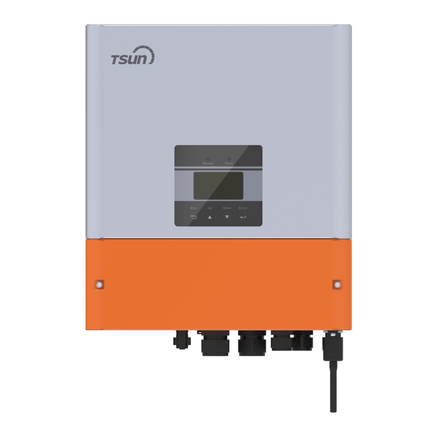
3.4 Terminals of inverter Object Description Battery connection area Waterproof valve EPS output GRID output BMS/Meter DI/DO WiFi/RF port for external Pocket WiFi/RF Warning! Qualified electrician will be required for the installation. -
Page 19: Technical Data
4 Technical Data 4.1 AC output / input TSOL-A3. TSOL-A3. TSOL-A4. TSOL-A4. TSOL-A5. TSOL-A6. Model 0K-H 6K-H 0K-H 6K-H 0K-H 0K-H AC output Nominal AC power [W] 3000 3680 4000 4600 5000 6000 Max. apparent AC power [VA] 3000 3680 4000 4600 5000... -
Page 20: Efficiency, Safety And Protection
4.3 Efficiency, Safety and Protection TSOL-A3. TSOL-A3. TSOL-A4. TSOL-A4. TSOL-A5. TSOL-A6. Model 0K-H 6K-H 0K-H 6K-H 0K-H 0K-H MPPT efficiency 99.90% Euro efficiency 97.00% Max. efficiency 97.80% Max. Battery discharge efficiency 97.00% (BAT to AC) (@full load) Safety & Protection Over/under voltage protection DC isolation protection Monitoring ground fault protection... -
Page 21: General Data
4.5 General Data TSOL-A3. TSOL-A3. TSOL-A4. TSOL-A4. TSOL-A5. TSOL-A6. Model 0K-H 6K-H 0K-H 6K-H 0K-H 0K-H 400*460*170 Dimension [W/H/D] (mm) Dimension of packing [W/H/D] (mm) 500*610*290 Net w eight [kg] Gross w eight [kg] Wall-mounted Installation Operating temperature range [℃] -20~+60 (Derating at 45) Storage temperature [℃] -20~+60... -
Page 22: Installation
5 Installation 5.1 Check for Physical Damage Make sure the inverter is intact during transportation. If there is any visible damage, such as cracks, please contact your dealer immediately. 5.2 Packing Object Description Inverter Bracket 4 Expansion tubes & 4 Expansion screws Battery connectors (1*positive, 1*negative) 4 Cord end terminals 6AWG and 5 Cord end terminals 10AWG for Version I... -
Page 23: Installation Precaution
Quality certification Product manual 5.3 Installation Precaution Installation Precaution TSOL Series inverter is designed for outdoor installation (IP 65). Make sure the installation site meets the following conditions: Not in direct sunlight. Not in areas where highly flammable materials are stored. ... -
Page 24: Space Requirement
5.4 Space Requirement 300mm Position Min. Size Side 300mm 300mm 300mm 300mm Bottom 300mm Front 300mm 300mm 5.5 Installation steps Tools required for installation. Installation tools: crimping pliers for binding post and RJ 45, screwdriver, manual wrench andφ8 driller. Step 1: Screw the wall bracket on the wall Place the bracket on the wall and mark down the position of the 4 holes. - Page 25 Step1 Step2 Fasten the inverter on the back board with screws M5*12 (the same as the other side). Recommended installation of anti-theft lock (user owned). Step3...
-
Page 26: Electrical Connection
6 Electrical Connection 6.1 Grid Connection TSOL series inverter is designed for single phase grid. Voltage is 220/230/240V, frequency is 50/60Hz. Other technical requests should comply with the requirement of the local public grid. Table 4: Cable and Micro-breaker recommended TSOL-A3.0 TSOL-A3.6 TSOL-A4.0... -
Page 27: Eps Connection (Apply To O Version And I Version Only)
Step4. Insert AC cable into Grid port through screw cap and then tighten the screw cap. Insert L wire and N wire into corresponding ports of AC terminal. Compress the PE wire with earth terminal, a screw it on the grounding stud. Step2 Step4 L-Gri d a nd N-Grid wires connection... - Page 28 O Version & I Version TSOL series inverter provides two versions for customer to choose based on the local rules. “O Version”means inverter needs to install an outer changeover device for EPS function. This version applies to the wiring rules which allow Neutral line of alternative supply can be isolated or switched (applies to most of the countries).
- Page 29 O Version O Version EPS breaker O Version O Version EPS breaker Please contact our sales for any compatible connector purchase requirement. Note! In case of discrepancies between wiring mode of local policy and the operation guide above, especially for the wiring of neutral line, grounding and RCD, please contact us before any operation!
- Page 30 Connection Steps: Step1. Make EPS wires. 1.1 Choose the appropriate wire (cable size: refer to picture below). 1.2 Reserve about 60mm of conductor material sectional area. 1.3 Remove 12mm of insulation from the end of wire. 1.4 Insert stripped wires into AC terminal and insure all conductor strands are captured in the AC terminal.
- Page 31 Requirements for EPS load Warning! Make sure the EPS load power rating is within EPS output rating, otherwise the inverter will shut down with an “over load” warning. When an “over load” is appeared, adjust the load power to make sure it is within the EPS output power range, then turn the inverter back on.
-
Page 32: Battery Connection
6.3 Battery Connection Charging & discharging system of TSOL series inverter is designed for high-voltage lithium battery. Before choosing battery, please note the maximum voltage of battery can not exceed 400V and the rated voltage of battery can not exceed 350V, and the battery communication should be compatible with TSOL inverter. - Page 33 Note: When working with Pylontech batteries, it is recommended the number of battery module (H48050-15S) is 2-7 and the number of battery manager system (SC0500A-100S) is 1. BMS PIN Definition Communication interface between inverter and battery is CAN with a RJ45 connector. Definition BMS_CANH BMS_CANL Note!...
- Page 34 Step5 Note: BAT port, not PV port! Note: The positive line and negative line are not allowed to access anti -Line. Communication Connection Steps: Step1. Disassemble the BMS/Meter cable gland. Step2. Prepare a communication cable (without sheath) and insert the communication cable through the cable nut.
-
Page 35: Meter Connection
6.4 Meter Connection Meter is used for monitoring the power usage for entire house, in the meantime, inverter will also need the data from Meter to achieve the Export Control Function. Note! It is necessary to connect meter to inverter otherwise inverter will shut down with a“Meter fault”alert. -
Page 36: Drm Connection
Step3 Step4 6.5 DRM Connection DRM is provided to support several demand response modes by emitting control signals as below. Note: pin definitions as below. DRM1/5 DRM2/6 DRM3/7 DRM4/8 +3.3V DRM0 DRM Connection Steps: Please refer to BMS connection steps for RJ45 connection. Please kindly note the PIN definition and port position will be slightly different. -
Page 37: Terminal Block Connection
6.6 Terminal Block Connection TSOL series inverter is equipped with multiple terminals to meet the extra needs of the user as below: RS485B RS484A ○ ○ (NO1) BAT-TEMP Turn off the switch to shut down the inverter remotely. ①... -
Page 38: Rf Connection (Optional)
WiFi Connection Steps: Step1. Plug Pocket Wifi into “WiFi” port at the bottom of the inverter. Step2. Build the connection between the inverter and router . Step3. Create a user account online (Please check the Pocket WiFi user manual for more details). - Page 39 Check the inverter: Step1. Check the status of indicators and LCD screen. The left indicator should be green and the indicator screen should display the main interface. Note! If the right indicator is red please check below the three points: - All the connections are correct.
- Page 40 Self-test in accordance with CEI 0-21(applies to Italy only) The self-test is only required for inverters, which are commissioned in Italy. The Italian standard requires that all inverters feeding into the utility grid are equipped with a self-test function in accordance with CEI 0-21. During the self-test, the inverter will consecutively check the protection reaction times and values for over -voltage, under-voltage, over-frequency and under-frequency.
-
Page 41: Setting
7 Setting 7.1 Control Panel Object Name Description Display the information of the inverter. Screen lit in green: The inverter is in normal status. flash in green: The inverter is in wait status. Indicator Off: The inverter is in fault status. lit in red: The inverter is in fault status. -
Page 42: Menu Structure
7.2 Menu Structure Output Battery Output Yield Bat Charge Bat Discharge EPS Yield Charge From Grid Event List Safety Date Time Italy Auto Test Buzzer Work Mode Advanced (Need Password) Bat.Para. Yield Model Export Limit Reset EPS Status Reset Event List DSP1 SW Factory Default DSP2 SW... - Page 43 7.3.2 status The status function contains four items instantaneous data of the inverter. There are inverter output data, battery data, EPS data. 7.3.3 History The history function contains seven items data of the inverter. There are inverter output yield, battery charge yield, battery discharge, eps yield, battery charge from grid yield, event list. 7.3.4 Setting The setting function contains three items data of the inverter.
-
Page 44: Quick Start Settings
7.3.8 Work Mode There are five work modes for choice. Parameter Comment The external generator generated power will be used to supply the local loads firstly, then to charge the battery. The redundant power Self Use will export to the public grid. (default) When there is no external generator supplied, battery will discharge for local loads firstly, and grid will supply power when... - Page 45 Date Time 2019-01-01 00:00 -OK- 7.4.2 safety User can set safety standard according to different countries and grid tied standards. Safety VDE 0126 -OK- 7.4.3 export limit power User can set the power value to allows the inverter able to control energy. The value range from 0 to 6000.
-
Page 46: Troubleshooting
8 Troubleshooting 8.1 Trouble shooting This section contains information and procedures for solving possible problems with TSOL Series Hybrid inverters, and provides you with troubleshooting tips to identify and solve most problems that could occur with the TSOL inverters. This section will help you narrow down the source of any problems you may encounter. Please read the following troubleshooting steps. - Page 47 • The system will back to normal if the grid is back. • Or seek for help from us. DCI over current protection Fault. • Or seek for help from us. DCI OCP Fault • Wait for a while to check if back to normal. DCV EPS over voltage protection Fault.
- Page 48 — Are the configurations settings correct for your particular installation? — Are the display panel and the communications cable properly connected and undamaged? Contact TSUNESS Customer Service for further assistance. Please be prepared to describe details of your system installation and provide model and serial number of the unit.
-
Page 49: Routine Maintenance
8.2 Routine maintenance Inverters do not need any maintenance or correction in most condition, but if the inverter often loses power due to overheating, this can be the following reason: The cooling fins on the rear of house are covered by dirties. Clean the cooling fins with a soft dry cloth or brush if necessary. -
Page 50: Decommissioning
9 Decommissioning 9.1 Remove the Inverter Disconnect the inverter from DC Input and AC output. Wait for 5 minutes for de-energizing. Disconnect communication and optional connection wiring. Remove the inverter from the bracket. Remove the bracket if necessary 9.2 Packaging Please pack the inverter with the original packaging. -
Page 51: Warranty Card
10 Warranty Card Customer Information ☆ Name: ☆ Address: City: State: Zip Code: Tel: Fax: E-mail: System Information ☆ Model of Products: System Commissioning Date: ☆ Date of Bill of Lading: No. of Products Used: ☆ No. of Fault Products: ☆...
Need help?
Do you have a question about the TSOL-A3.0K-H and is the answer not in the manual?
Questions and answers