Table of Contents
Advertisement
Quick Links
Tri-One
klick to
klick to
www
www
u-s-v
Y O U R C O N N E C T I O N TO S A F E T Y
ACDC-DCDC
Three-phase in/Single-phase out UPS
klick to
www
Y O U R C O N N E C T I O N TO S A F E T Y
Y O U R C O N N E C T I O N TO S A F E T Y
SYSTEME
10K
15K-20K
-
Uninterruptible Power Supplies
klick to
www
Y O U R C O N N E C T I O N TO S A F E T Y
CONTACT
YOUR CONNECTION TO SAFETY
klick to
www
Y O U R C O N N E C T I O N TO S A F E T Y
CALLBACK
Advertisement
Table of Contents

Related Manuals for Thiele Tri-One 10000

Summary of Contents for Thiele Tri-One 10000
- Page 1 YOUR CONNECTION TO SAFETY Tri-One 15K-20K Three-phase in/Single-phase out UPS Uninterruptible Power Supplies klick to klick to klick to klick to klick to u-s-v Y O U R C O N N E C T I O N TO S A F E T Y Y O U R C O N N E C T I O N TO S A F E T Y Y O U R C O N N E C T I O N TO S A F E T Y Y O U R C O N N E C T I O N TO S A F E T Y...
-
Page 2: Table Of Contents
YOUR CONNECTION TO SAFETY Contents 1. Safety 1.1 Safety instructions 1.2 Symbol description 2. Product introduction 2.1 UPS view 2.2 UPS operating principles 2.3 Applications 2.4 Characteristics 2.5 UPS models 3. Installation 3.1 Unpack checking 3.2 Installation procedure 3.3 UPS input and output connections 3.4 Connection of UPS communication cables 3.5 External battery connection (for extended autonomy time only)) 4. -
Page 3: Safety
YOUR CONNECTION TO SAFETY 1. Safety This section will introduce you to the symbols and to considerations about safety of Tri-One series. Pay attention to the contents of this section before each operation on the equipment. Contact your reseller or distributor beforehand in case Ups should be used for particular applications that have direct contact with people's lives, such as medical equipment, elevators, or similar, and he will advise you in the proper way. -
Page 4: Symbol Description
YOUR CONNECTION TO SAFETY 1.2 Symbol Description The safety symbols included in this manual are shown in the table below, which are used to inform users of safety issues that should be obeyed when installation, operation and maintenance. SIMBOLO SPIEGAZIONE SIMBOLO SPIEGAZIONE SIMBOLO... -
Page 5: Product Introduction
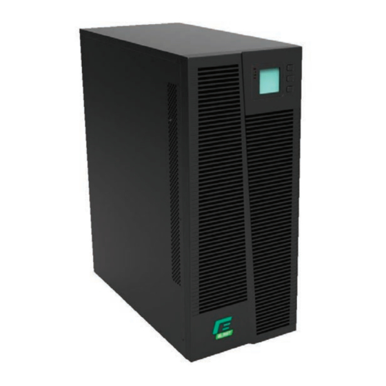
YOUR CONNECTION TO SAFETY 2. Product Introduction 2.1 UPS view UPS front view (all models) 10KVA – Rear view 15-20KVA – Rear view Ver02 17.11.2014 klick to klick to klick to klick to klick to u-s-v Y O U R C O N N E C T I O N TO S A F E T Y Y O U R C O N N E C T I O N TO S A F E T Y Y O U R C O N N E C T I O N TO S A F E T Y Y O U R C O N N E C T I O N TO S A F E T Y... -
Page 6: Ups Operating Principles
YOUR CONNECTION TO SAFETY 1) Manual By-Pass 2) Parallel Port 1 (disabled) 3) Parallel Port 2 (disabled) 4) Intelligent Slot for Relay / SNMP card (cards are optional) 5) EPO connector 6) COM port (RS232) 7) USB port 8) Input/Output switches 9) Terminal blocks (Input/Output/Batteries) UPS operating principles The system can work as a single unit or parallel one, so as to enhance its reliability... -
Page 7: Applications
YOUR CONNECTION TO SAFETY Applications This series UPS, providing reliable AC power to various equipment, can be used for computer center, network management center, auto control system, telecom systems, etc Characteristics This series is an intelligent online sine wave UPS. High frequency, double conversion, high input power factor, wide input voltage range, the output will not be disturbed by power network, suitable for area with poor power supply condition. -
Page 8: Installation
YOUR CONNECTION TO SAFETY Installation Unpack checking 1) Don’t lean the UPS when moving it out from the packaging. 2) Check the appearance to see if the UPS is damaged during transportation, do not switch on the UPS if any damaged is found and please contact the dealer. Check the accessories according to the packing list and contact the dealer if any parts missing Verify that UPS is suitable for your application, by checking the characteristics of... -
Page 9: Ups Input And Output Connections
YOUR CONNECTION TO SAFETY UPS input and output connections Sizing of the cables at input, output and battery, please refer to the below table: 1) Switch Off all breakers before connecting cables.. 2) Remove the cover of terminal blocks and connect the cables correspondingly. Connect the UPS output L, N, E to L, N, E of load via a PDU. -
Page 10: External Battery Connection (For Extended Autonomy Time Only))
YOUR CONNECTION TO SAFETY External battery connection (for extended autonomy time only) Make sure that battery quantity complies with the spec. (16/18/20 blocks at 12V in series). Make sure that the voltage of battery bank is 192/216/240Vdc. CAUTION: Don’t mix batteries with different capacity & brands and don’t mix brand new and old batteries Standard configuration is made by 16 blocks with a max. -
Page 11: Control Panel, Configuration And Operation
YOUR CONNECTION TO SAFETY UPS may have voltage at its output even when mains is not present. Switch Off the input breaker and then switch Off the UPS, to avoid any voltage to the load. If a laser printer must be connected to the output of UPS, select a device with an output power suitable to handle the current peak of the printer. -
Page 12: Control Panel
YOUR CONNECTION TO SAFETY Press “On” on the front panel to start the UPS and in the meantime, the LCD display will light up. You may view the data and set parameters on the LCD display and the LED display of the UPS will show the latest status of the UPS. - Page 13 YOUR CONNECTION TO SAFETY When UPS is supplied by the mains the message on display is the following: 01 – Status and operating mode 1) Operating mode are “NOR” or “ECO”. 2) Press “scroll” button, the UPS goes to next page and the display will show the following: 02 –...
- Page 14 YOUR CONNECTION TO SAFETY % of load 08 - Load 09 - PFC/Internal temp. (up) and ambient temp. (down) 10 - DC Bus voltage 11 – DSP software version and UPS model Alarm code (see section 4.6.2) When UPS is charging the battery, the following information are displayed: Charge status I n p u t Input...
-
Page 15: Parameters Setting
YOUR CONNECTION TO SAFETY Pressing “scroll” button, you may circulate all messages from the first one to the last one then returns back to the first one 5) All alarm codes are present when abnormal behavior(s) occur(s). The display value of the above parameter will update within 0.2s Parameters setting The setting function is controlled by 3 buttons (Enter (, Off ▲, On ▼): Enter (---goes into the setting page and value adjustment;... - Page 16 YOUR CONNECTION TO SAFETY When under the mode setting press On▼ or when under frequency setting press Off▲, it goes to the output voltage setting. The output voltage line flashes as in above picture. Use button Enter to choose the different output voltage. There are 3 different voltages---220, 230, 240.
- Page 17 YOUR CONNECTION TO SAFETY When under the frequency setting press On▼ or when under battery quantity setting press Off▲, it goes to the battery capacity setting. The battery capacity line flashes as in above picture. • Use button Enter to choose the different battery capacity. Battery capacity range is 1-200Ah.
- Page 18 YOUR CONNECTION TO SAFETY 4.4.6 Bypass upper voltage level setting Bypass upper voltage level setting (Note: Inside the broken-line is the flashing part.) When under the battery quantity setting press On▼ or when under bypass voltage lower setting press Off▲, it goes to the bypass upper limit setting.
-
Page 19: Working Mode And Switching
YOUR CONNECTION TO SAFETY 4.4.8 Buzzer mute setting Buzzers mute setting (Note flashing part in dashed box) Press ON under bypass voltage lower limit setting or press OFF under the parallel ID setting can enter the buzzer setting. Now the setting status is flashing as the Figure 14 shows (note: on=mute; off= no mute). When press, it shows the mute cycle setting, the selection includes ON and OFF. -
Page 20: Led And Message On Display
YOUR CONNECTION TO SAFETY LED and messages on display This section lists the event and alarm messages that the UPS might display. This section is liste d with each alarm message to help you troubleshoot problems 4.6.1 Operating status CODE STATUS ALARM BY-PASS... - Page 21 YOUR CONNECTION TO SAFETY 4.6.2 Alarms Information CODE UPS ALARM WARNINGS BUZZER ALARM LED ALARM Rectifier Fault Inverter fault Inverter Thyristor short Inverter Thyristor broken Bypass Thyristor short Bypass Thyristor broken Fuse broken (Reserved) Parallel relay fault Fan fault Continuous beep Reserved (EPO) Auxiliary power fault Initialization fault...
-
Page 22: Maintenance
YOUR CONNECTION TO SAFETY CAUTION: The following procedure must be implemented if UPS is connected to a genset, which should have a power twice the UPS minimum: Start up the genset and when its voltage is stable connect the UPS to genset output. Then start up the UPS and connect its load gradually. -
Page 23: Ups Features
YOUR CONNECTION TO SAFETY A Switch on the input breaker AC norm l but AC indicator off, A Input circuit breaker off. B Input power the UPS is in battery mode connection problem B Check the connection and re-do Check the connection and re-do No alarm but no outpu Output connection problem A Press and hold On button for 1s... -
Page 24: Environment
YOUR CONNECTION TO SAFETY synchronization 0.5Hz/s (units in parallel) 105 % ~ 110 % lasts max 1h 110% ~ 125%,lasts max 10 min Overload with mains 125% ~ 150%, lasts max 1 min 150% switch to bypass Load for a long time when rated output current under 125% Bypass overload Bypass load capacity is controlled by bypass circuit breaker, tripping when circuit breaker operating current. -
Page 25: Communication Interface
YOUR CONNECTION TO SAFETY Depth (mm) Weight (Kg) Color Black Communication interface This UPS has a DB9 standard interface on rear panel, with the following pinout: DEFINITION 1-4-6-7-8-9 Not used When connection the UPS to a PC via a RS232 cable, please use a standard cable with the following connections: CONNECTOR 1 (female) on CONNECTOR 2 (male) on... -
Page 26: Packaging Contents
YOUR CONNECTION TO SAFETY Packaging contents MODEL ● Instruction manual ● Software (CD-ROM) RS232 cable USB cable EPO connector ● О present optional Ver.00 22 Febbraio 2016 klick to klick to klick to klick to klick to u-s-v Y O U R C O N N E C T I O N TO S A F E T Y Y O U R C O N N E C T I O N TO S A F E T Y Y O U R C O N N E C T I O N TO S A F E T Y Y O U R C O N N E C T I O N TO S A F E T Y... -
Page 27: Warranty
YOUR CONNECTION TO SAFETY WARRANTY Dear Customer, Thank you for purchasing a NAICON product. We hope that you be satisfied. If the product fails in warranty period, please contact your dealer or call +39 02 950031 or go to www.naicon.com/elsist. Before contacting your dealer or authorized service network, we recommend that you read the operating and maintenance manual carefully.
Need help?
Do you have a question about the Tri-One 10000 and is the answer not in the manual?
Questions and answers