Table of Contents
Advertisement
Advertisement
Table of Contents

Related Manuals for Evoqua IONPURE IP-POWERDSP-G2

Summary of Contents for Evoqua IONPURE IP-POWERDSP-G2
- Page 1 ® IONPURE G2 DISPLAY BOARD For use with G2 Power Controllers Operation & Maintenance Manual IP-POWERDSP-G2MAN November 2011 Revision 1 Manual Covers Part #: IP-POWERDSP-G2 10 Technology Drive Lowell, Massachusetts 01851 Tel: (866) 876-3340 Fax: 978-934-9499 www.ionpure.com...
-
Page 2: Table Of Contents
® IONPURE G2 DISPLAY BOARD – IP-POWERDSP-G2 Table of Contents DISCLAIMER STATEMENT ........................4 PROPRIETARY RIGHTS STATEMENT ....................4 MANUAL REVISION HISTORY......................4 INTRODUCTION ..........................5 1.1 Caution and Warning Messages ....................5 1.2 General Description ........................5 INSTALLATION..........................7 2.1 Requirements.......................... - Page 3 ® IONPURE G2 DISPLAY BOARD – IP-POWERDSP-G2 Figure 6: Current Range Selection DIP Switch ..................10 Figure 7: Control/Navigation Keys ....................... 12 Figure 8: Menu Tree Structure......................13 Figure 9: OVERVIEW Screen Example ....................14 Figure 10: RUN Screen – Page 1 ......................14 Figure 11: RUN Screen –...
-
Page 4: Disclaimer Statement
® IONPURE G2 DISPLAY BOARD – IP-POWERDSP-G2 Disclaimer Statement The operation and maintenance manual should provide complete and accurate information to meet your operating and/or service requirements based on the information available at the time of publication. The information in this manual may not cover all operating details or variations or provide for all conditions in connection with installation, operation and maintenance. -
Page 5: Introduction
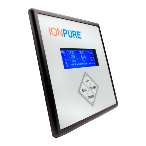
® IONPURE G2 DISPLAY BOARD – IP-POWERDSP-G2 1 Introduction 1.1 Caution and Warning Messages WARNING and CAUTION labels are used to attract attention to essential or critical information in this manual. The labels are located to the left of the associated messages. Caution and Warning messages will be located immediately before related text. - Page 6 ® IONPURE G2 DISPLAY BOARD – IP-POWERDSP-G2 The display board employs a 20 X 4 LCD backlit display for a clear view of data under most lighting conditions. Parameters can be adjusted and screens can be navigated using the four membrane switches on the front panel.
-
Page 7: Installation
® IONPURE G2 DISPLAY BOARD – IP-POWERDSP-G2 2 Installation 2.1 Requirements The G2 Display Board meets NEMA 4/IP65 requirements when properly installed. The unit is intended to be mounted into an enclosed panel with the supplied gasket to provide a seal at the panel cutout and it is secured from the back with the provided nuts. -
Page 8: Panel Mount
® IONPURE G2 DISPLAY BOARD – IP-POWERDSP-G2 2.2 Panel Mount To mount the G2 display into a panel: a. Prepare a cutout and four mounting holes in the door of the panel as shown in Figure 3. All cutouts should be clean and free of burrs. Figure 3: Panel Cutout Dimensions b. -
Page 9: Connections To Multiple G2 Power Controllers
® IONPURE G2 DISPLAY BOARD – IP-POWERDSP-G2 c. Once the power controller is turned on, the display should power on. Figure 4 illustrates the connections described above: Figure 4: Connections to a Single G2 Power Controller 2.3.2 Connections to Multiple G2 Power Controllers To connect the G2 display to multiple G2 power controllers: a. -
Page 10: Power Controller Setup
® IONPURE G2 DISPLAY BOARD – IP-POWERDSP-G2 Figure 5: Connections to Multiple G2 Power Controllers 2.4 Power Controller Setup 2.4.1 DC Output Current Range Selection To limit the possibility of applying excessive current to a CEDI module, it is recommended to select an appropriate output current range with DIP switch SW1 of the G2 Power Controller as described in Figure 6. -
Page 11: Unit Id Selection
® IONPURE G2 DISPLAY BOARD – IP-POWERDSP-G2 The G2 display will detect the selected current range upon startup and will limit the DC output current setpoint (A DC out) to this range. 2.4.2 Unit ID Selection A unique identification number/letter needs to be assigned to each power controller that is connected to a G2 display so they can be recognized without conflicts. -
Page 12: Operation
® IONPURE G2 DISPLAY BOARD – IP-POWERDSP-G2 3 Operation 3.1 Control/Navigation Keys Figure 7: Control/Navigation Keys ESC: press to exit a submenu, deactivate the cursor or discard setpoint changes. UP: press to see the previous page of information or select between submenus or configurable setpoints. -
Page 13: Menu Structure
® IONPURE G2 DISPLAY BOARD – IP-POWERDSP-G2 3.2 Menu Structure Figure 8: Menu Tree Structure OVERVIEW: this is the startup screen. It displays 3 channels at a time and shows the CEDI module’s identification number (selected on the G2 Power Controller via switch SW2), DC output volts, DC output current and module resistance in ohms. -
Page 14: Figure 9: Overview Screen Example
® IONPURE G2 DISPLAY BOARD – IP-POWERDSP-G2 Figure 9: OVERVIEW Screen Example RUN: this submenu provides operational data and access to adjust the DC output current of the selected power controller, as well as access to submenus SETUP, ALARMS, LOGS and DIAGNOSTICS. -
Page 15: Figure 11: Run Screen
® IONPURE G2 DISPLAY BOARD – IP-POWERDSP-G2 48 hours of cumulative operation from the initial startup. Resistance values above 999.9 are represented as “***HI”. PAGE 2: Figure 11: RUN Screen – Page 2 Ohms chg%: percentage of change in CEDI module resistance from initial (Ohms init) to present (Ohms pres). -
Page 16: Figure 13: Run Screen
® IONPURE G2 DISPLAY BOARD – IP-POWERDSP-G2 Op.hours: hours in operation since the initial startup. Time is accrued only while the Remote ON/OFF input of the power controller is closed. Ic (VDC): estimated value of analog signal between terminals Ic+/Ic- of the selected power controller. -
Page 17: Figure 15: Setup Screen
® IONPURE G2 DISPLAY BOARD – IP-POWERDSP-G2 DIAGNOSTICS: press ENTER to access the DIAGNOSTICS submenu. SETUP: this submenu provides access to adjust the following settings: Ohms limit, VDC limit, Ext control, Change password? and Change module? This submenu is protected by a 4-digit password. The factory default password is 0000 and it can be changed by the user. -
Page 18: Figure 16: Setup Screen
® IONPURE G2 DISPLAY BOARD – IP-POWERDSP-G2 Change password?: press ENTER and use the UP/DOWN keys to change the password of the SETUP submenu. PAGE 2: Figure 16: SETUP Screen – Page 2 Change module?: it is recommended to use this option to reset all historic data after a module replacement. -
Page 19: Figure 18: Alarms Screen
® IONPURE G2 DISPLAY BOARD – IP-POWERDSP-G2 Clear alarms?: if any alarms are active, pressing ENTER on this page will activate the cursor to change the “N” to “Y” using the UP or DOWN arrows. Pressing ENTER once “Y” is selected will clear all alarms that are active (not “ok”). -
Page 20: Figure 19: Logs Screen
® IONPURE G2 DISPLAY BOARD – IP-POWERDSP-G2 Figure 19: LOGS Screen MAX VALUES: displays maximum values of important parameters to help with performance analysis and troubleshooting. These values are monitored continuously while the DC output of the power controller is enabled (closed remote ON/OFF input). Figure 20: MAX VALUES Screen VAC: maximum registered AC input voltage to the selected power controller. -
Page 21: Figure 21: Min Values Screen
® IONPURE G2 DISPLAY BOARD – IP-POWERDSP-G2 MIN VALUES: displays minimum values of important parameters to help with performance analysis and troubleshooting. These values are monitored continuously while the DC output of the power controller is enabled (closed remote ON/OFF input). Figure 21: MIN VALUES Screen VAC: minimum registered AC input voltage to the selected power controller. -
Page 22: Figure 22: Module Ohms&Amps Screen
® IONPURE G2 DISPLAY BOARD – IP-POWERDSP-G2 Figure 22: MODULE OHMS&S Screen DIAGNOSTICS: this submenu provides the firmware revisions of the selected power controller, the display and the results of the power controller’s self test routine. Figure 23: DIAGNOSTICS Screen DCPC rev: firmware revision of the power controller. -
Page 23: Getting Started
® IONPURE G2 DISPLAY BOARD – IP-POWERDSP-G2 4 Getting Started 4.1 Initial Startup The startup sequence depends on the design of the CEDI system. Please consult the Operation Manual for the CEDI system. The following startup procedure is only an example for a typical single module CEDI system: Close the main disconnect switch (or circuit breaker) for the CEDI system. -
Page 24: Troubleshooting
® IONPURE G2 DISPLAY BOARD – IP-POWERDSP-G2 5 Troubleshooting Table 2: Troubleshooting Condition Possible Causes Action Display does not power on Bad or incorrect Ethernet cable Verify that cable is good Cable should NOT be crossover Power controller not energized Energize power controller A channel displays asterisks Bad or incorrect Ethernet cable... -
Page 25: Appendix - Ul And Ce Compliance
® IONPURE G2 DISPLAY BOARD – IP-POWERDSP-G2 APPENDIX – UL and CE Compliance UL (US/CANADA) The G2 display board was evaluated as an accessory of the G2 power controller. Both are recognized by UL through compliance with the following standards: •...
Need help?
Do you have a question about the IONPURE IP-POWERDSP-G2 and is the answer not in the manual?
Questions and answers