Advertisement
船舶用親時計
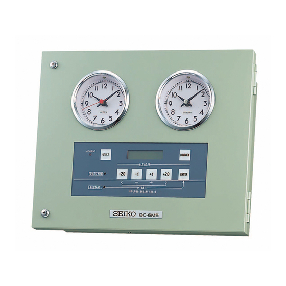
MARINE MASTER CLOCK
QC-6M5
このたびはセイコ-船舶用親時計QC-6M5をお買い上げいた
だきまして、まことにありがとうございました。
この取扱説明書を最後までお読みのうえ、正しくお取り扱いいた
だきますようお願いいたします。
なお、取扱説明書は大切に保管しておいてください。
Thank you so much for purchasing Seiko Marine Master Clock
QC-6M5.
Before putting your QC-6M5 to use, please be sure to read this
manual carefully as it has been prepared to assist in the
installation, operation and maintenance of your QC-6M5.
You are recommended to keep this manual for future
reference.
Advertisement
Table of Contents

Related Manuals for Seiko QC-6M5


Summary of Contents for Seiko QC-6M5
- Page 1 Thank you so much for purchasing Seiko Marine Master Clock QC-6M5. Before putting your QC-6M5 to use, please be sure to read this manual carefully as it has been prepared to assist in the installation, operation and maintenance of your QC-6M5.
- Page 2 (4) 本製品がお客様により不適当に使用されたり、 (4) SEIKO shall not be liable for any failures of the products 本書の内容に従わずに取り扱われたり、または or direct or indirect damages resulting from such failures 当社および当社指定のサービス部門以外の第三...
-
Page 3: Table Of Contents
-目次- -Contents- Page SAFETY PRECAUTIONS ■ 安全のために必ずお守りください 4 INSTALLATION & WIRING ■ 取付と結線 5 1.親時計の取付け 5 INSTALLING THE MASTER CLOCK 2.電源・子時計との結線 6 WIRING TO POWER SUPPLY AND SECONDARY CLOCKS. HANDLING METHOD ■ 取扱い方法 7 1.電源を入れる前に 7 INSPECTION BEFORE TURNING THE POWER SWITCH ON 2.初期設定... - Page 4 If a foreign object is allowed into a 一、これらが内部に混入した Prohibition of hole or gap by mistake, disconnect 場合は速やかに電源スイッチ allowing the main switch, and call your SEIKO を切ってください。点検は、 foreign agent or dealer for inspection and 弊社もしくは代理店にご依頼 objects in servicing. If left uncorrected, this ください。そのまま使うと感電...
- Page 5 ■INSTALLATION & WIRING ■取付と結線 1.親時計の取付け 1.INSTALLING THE MASTER CLOCK ① 壁掛型 ①Wall mounting type 4ヶ所の取付穴を利用し、 壁面にボルトで固定 Fix the master clock to a wall surface with four. して下さい。 installation holes Installation dimensions are indicated in Fig.1. 6mm 取付寸法は図の通りで、ボルト径は6mmが dia. bolts are suitable. 適当です。...
- Page 6 2.電源・子時計との結線 2.WIRING TO POWER SUPPLY AND SECONDARY CLOCKS ① 取付前に全ての子時計の針を同一時刻 ① Before installation, synchronize all secondary に合わせます。 (例えば12時0分0秒) clocks. (Ex.12hr 0min 0sec) ② 入線穴の選択 ②Selection of service inlet 親時計は背面および下面に入線穴があり下 The master clock is provided with two service 面にかくし板が取付けてあります。 入線穴と inlets on the back and bottom. The bottom inlet is して下面を利用する場合は、...
- Page 7 ■HANDLING METHOD ■取扱い方法 1.電源を入れる前に 1.INSPECTION BEFORE TURNING THE POWER SWITCH ON ① 内部の部品やプリント基板、ねじ等がゆる ①Check on loosened inner parts, printed circuit んでいないか点検します。 boards, screws and so on. ② 結線工事の際の電線くず等が付着していな ②Check on the adhesion of wire chips generated いか点検します。 when working on installation. ③...
- Page 8 ⑤ この親時計は過電流防止回路付で各出力 ⑤ The master clock equipped with 信号は半導体送出となっています。 over-current limiter and its output signals are 配線間の絶縁および過負荷にご注意くださ generated from solid-state switches. Insulate the い。 field wiring with utmost care. Also make sure not 各子時計の電流容量は下表の通りです。 to overload the master clock. Current capacity of each secondary clock is as follows.
-
Page 9: 操作パネル
2.初期設定 2.STARTING OPERATION 2-1 操作パネル Operation Panel ALARM デジタル表示部 UT/LT DIMMER DIGITAL DISPLAY PART LT ADJ SEC ADJ ENTER < > RESTART UT / LT / SECONDARY HANDS ※文中のデジタル表示の表記について ※ ABOUT DIGITAL DISPLAY " " 点滅を意味します ABC ABC ABC BLINKING "... - Page 10 2-3 操作 Operation ① “AC(U11)”、“DC(U15)”、 ①Please turn all three breakers of "AC (U11)", " “ O U T P U T ( U 9 ) ” の 3 つ の DC (U15)", and "OUTPUT (U9)" on. The LED lamp (yellow) for the dial illumination ブレーカを全て「ON」にしてください。...
- Page 11 ④ 下記の画面が表示されます。 ④The following screen is displayed. SET 00/01/01 UT 00:00:00.0 → 「0.5秒子時計」‥‥停止→手動調整 0.5sec secondary clock・・・・stop→Manual adjustment 「30秒子時計」 ‥‥停止 30sec secondary clock・・・・stop 本体に「UT」(協定世界時)を入力してくだ Set “UT”, (universal time). さい。 + - < > で点滅部を移動、 で点滅部 Move Input-frame (blinking part) by < key or > の数値を調整します。...
- Page 12 ⑤ 下記の画面が表示されます。 ⑤The following screen is displayed. SET 01/07/29 LT 10:03:10. → 「0.5秒子時計」‥‥運針 0.5sec secondary clock・・・・running 「30秒子時計」 ‥‥停止 30sec secondary clock・・・・stop 本体に「LT」(シップタイム)を入力して Set “LT”. (ship time) ください。 + - < > で点滅部を移動、 で Move Input-frame (blinking part) by < key or > 点滅部の数値を調整します。...
- Page 13 > 指針位置の時刻の入力後、 で「→」の上 Please move the cursor to “→" by > key, after the input of the time of the hands position. にカーソルを移動してください。 The display becomes as follows. 次の表示になります。 PUSH ← 12:00:00 ENT 「0.5秒子時計」‥‥運針 0.5sec secondary clock・・・・running 「30秒子時計」 ‥‥停止 30sec secondary clock・・・・stop 入力した指針位置の時刻に間違いがなけれ...
-
Page 14: Ut」/「Lt」の表示切替
3.通常運用 3.NORMAL OPERATION 3-1 「UT」/「LT」の表示切替 3-1 SWITCH THE DISPLAY OF “UT" and “LT" 通常運用時は「UT」または「LT」のどち The time display shows UT or LT during normal operation. らかの表示を行います。 The display can be switched whenever UT/LT is UT/LTを押すごとに、 表示が切り替わり pushed. ます。 UT 01/07/29 LT 01/07/29 ←→... - Page 15 調針完了まで最長5分かかります。 調針が It takes maximum five minutes to complete the adjustment. When the adjustment is completed, 完了すると、次の表示(通常時)になりま it becomes the following display. す。 LT 01/07/29 19:14:00 「0.5秒子時計」‥‥運針 0.5sec secondary clock・・・・running 「30秒子時計」 ‥‥運針 30sec secondary clock・・・・running [修正時の動作] [OPERATION OF 0 SEC-ADJUSTMENT] (時刻進みの修正)...
-
Page 16: 時刻の自動修正
3-3 時刻の自動修正 3-3 AUTOMATIC TIME ADJUSTMENT 外部のGPSユニットを接続することにより The time of master clock can be automatically adjusted periodically by connecting an external 本機の時刻を定期的に自動修正します。 GPS unit. この場合、GPSユニットの出力する信号が The signal format from that unit should be NMEA0183に準拠していることが必要 conformed to NMEA0183. です。 To connect an external GPS unit to the GPSユニットの接続は、基板上の端子板に... -
Page 17: Lt」手動調整
3-4 「LT」手動調整 3-4 MANUAL LT ADJUSTMENT 「LT」を調整するには、「LT ADJ」用 Four keys ( -20 -1 +1 +20 ) are used to adjust LT. の - 2 0 - 1 + 1 + 2 0 の 4 つ の LT adjustment is effective only on the display of キーで行います。... -
Page 18: Lt」自動調整
3-5 「LT」自動調整 3-5 AUTOMATIC LT ADJUSTMENT GPSユニット使用時に、 船舶の位置によって Automatic LT adjustment is available when an external GPS unit is connected to the master 「LT」を自動的に調整することができます。 clock. 「LT」を自動調整するには、本機基板上の To do so, flip up the switch of “Automatic LT ト グ ル ス イ ッ チ 「 A u t o m a t i c Adjustment”... -
Page 19: 時計照明の調光
3-6 時計照明の調光 3-6 OPERATION OF DIMMER 内装の液晶表示器およびモニタ子時計の照明 Adjustment of the brightness of LCD and monitor の調光は、DIMMER キーで行います。 clock can be done by DIMMER key. 電源入力ラインの状態も確認できます。 The status of the input line of power supply can be DIMMER キーを1回押すと、次のような confirmed as well. 表示になります。... -
Page 20: 停電復帰
4.警報表示 4.ALARM DISPLAY 本機およびその接続線に異常が発生した場合 When a trouble on the system or the connected line is detected, the ALARM lamp (LED) blinks, the は、前面の警報表示ランプ(LED)が点滅し、 alarm signal output status 警報信号出力がONし、同時に液晶表示器に phenomenon displayed その現象を表示します。 simultaneously. 4-1 停電復帰 4-1 RESUMED FROM POWER FAILURE 停電復帰時には次の表示になります。 When the power is resumed from failure, it becomes the following display. -
Page 21: 出力停止
4-2 出力停止 4-2 SUSPENSION OF OUTPUT LINE 各子時計出力ラインおよびロガー出力ライン When abnormal condition is detected on the output line of secondary clocks or logger output, or の異常時や、電源入力(AC,DC双方)に input 異 常 が 発 生 し た 場 合 に は 次 の 表 示 に な り line of AC/DC power supply, the following status is ます。... -
Page 22: 電源異常
4-3 電源異常 4-3 ABNORMAL POWER SUPPLY 本機で使用の電源 (ACまたはDC) のいずれ When abnormal condition (lower voltage) is detected on the AC/DC power supply, か一方に異常(電圧低下)が発生すると、 次の表 the following status is displayed. 示になります。 ・AC ラインが異常の場合 For AC line WARNING UT 01/07/29 ←→ AC POWER 11:08:32... - Page 23 5.警報・ロガーの接続 5.CONNECTION OF ALARM AND LOGGER 警報信号およびロガー信号はトランジスタの Alarm signal and logger signal are output via circuit of “Transistor open-collector”. オープンコレクタ出力となっています。 接続例 Sample of connection COMMON ALARM LOGGER i :100mA 以下(警報) i :less than 100mA(ALARM) :150mA 以下(ロガー) :less than 150mA(LOGGER) R :リレー...
- Page 24 ■保守 下記のような現象がおきたときは、各項目をチェックしてください。 現 象 原 因 対 策 設置直後、または停電復帰。 初期設定を行う アラームランプ点滅 過負荷 子時計停止(過負荷時) 異常原因を取り除き、 (負荷のラインのショート) RESTARTを押す (子時計数オーバー) 0.5秒子時計と 30秒子時計が同期 時刻合わせの操作ミス 正しく操作する。 しない。 異常原因を取り除き、 DC用ブレーカ(U15) 過負荷 ブレーカを戻してから ま た は O U T P U T 用 (負荷のラインのショート) ブレーカ(U9)の動作 (子時計数オーバー) RESTARTを押す AC用ブレーカ(U11)...
- Page 25 ■EXTERNAL VIEW ■外形図 I-5321-4...
- Page 26 ■仕様 ・原振 水晶発振器(4.194304MHz) ・精度 日差±0.2秒以内 ・精度保証範囲 5℃~40℃ ・動作温度範囲 -10℃~55℃ ・内装時計 デジタル時計 16桁2行LCD表示器(文字高4.89mm) アナログ時計(MASTER) 中3針0.5秒運針時計(文字板径80mm) アナログ時計(SECONDARY) 2針30秒運針時計(文字板径80mm) ※内装時計はデジタル時計、アナログ時計とも、調光機能付き照明を内蔵 ・入出力 ・0.5秒子時計出力 2線式(正転のみ) 子時計20台接続可能(240mA以下) ・30秒子時計出力 3線式(正逆転) 子時計130台接続可能(1560mA以下) ・デジタル信号出力 平衡2線式(RS-422),1ポート NMEA0183準拠 ・デジタル信号入力 平衡2線式(RS-422),1ポート NMEA0183準拠 ・ロガー信号出力 5線式,1ポート (合計150mA以下) ・24V(COMMON) ・30秒有極信号出力(+) ・30秒有極信号出力(-) ・調針中信号出力(-) ・逆転中信号出力(-) ・警報信号出力 2線式,1ポート (100mA以下)...
- Page 27 ■ SPECIFICATIONS ・Crystal oscillation 4.194304MHz ・Accuracy daily rate within ±0.2 second ・Temperature range for guarantee accuracy +5℃~+40℃ ・Operating temperature range -10℃~+55℃ ・Equipped clocks Digital clock 16 digits two line liquid crystal display (STN half penetration type and character height 4.89mm) Analog clock ( MASTER ) Center-three-hands,0.5-second step,φ80mm dial Analog clock ( SECONDARY )
- Page 28 ■ アフタ-サービスの御用命は下記へお願い致します。 FOR AFTER-SALE SERVICE PLEASE CONTACT ● 株式会社ユウ・ピー・アイ ● GEORG HECHELMANN NACHF, GMBH. 〒231-0047 Randstrasse 30 横浜市中区羽衣町 2 丁目 5 番地 13 22525 Hamburg Tel:045-243-8090 Germany Fax:045-261-6111 Tel:(+49)40-5477760 Fax:(+49)40-54777666 Telex:2163852 NAVID ● U・P・I Co., LTD. 5-13, 2-Chome, Hagoromo-Cho ● KELVIN HUGHES NETHERLANDS LTD. Naka-ku, Yokohama 231-0047, Japan Klompenmarkerstraat 64 Tel:81-45-243-8090...
- Page 30 URL http://www.seiko-sts.co.jp I-5321-4...
Need help?
Do you have a question about the QC-6M5 and is the answer not in the manual?
Questions and answers