Advertisement
READ THESE INSTRUCTIONS BEF
D THESE INSTRUCTIONS BEFORE CONNECTING THE ACTUATOR
D THESE INSTRUCTIONS BEF
D THESE INSTRUCTIONS BEF
INSTRUCTIONS IS NOT COVERED UNDER WARRANTY.
INSTRUCTIONS IS NOT COVERED
INSTRUCTIONS IS NOT COVERED
INSTRUCTIONS IS NOT COVERED
ECP-Series electric actuators operate with the
ECP
lectric actuators operate with the use of live electr
lectric actuators operate with the
lectric actuators operate with the
adjust these actuators. Always ensure that the power supply is disconnected
adjust these actuators.
adjust these actuators.
Always ensure that the power supply is disconnected
Always ensure that the power supply is disconnected
Always ensure that the power supply is disconnected
Always ensure that the power supply is disconnected
prior to removing the top cover by disconnecting the DIN power input plug. It is stron
prior to removing the top cover by disconnecting the DIN power input plug. It is stron
prior to removing the top cover by disconnecting the DIN power input plug. It is stron
prior to removing the top cover by disconnecting the DIN power input plug. It is stron
prior to removing the top cover by disconnecting the DIN power input plug. It is stron
prior to removing the top cover by disconnecting the DIN power input plug. It is strongly
prior to removing the top cover by disconnecting the DIN power input plug. It is stron
prior to removing the top cover by disconnecting the DIN power input plug. It is stron
recommended tha
ommended tha
ommended that each actuator has its own independent fuse system to protect it from the
each actuator has its own independent fuse system to protect it from the
each actuator has its own independent fuse system to protect it from the
each actuator has its own independent fuse system to protect it from the
each actuator has its own independent fuse system to protect it from the
each actuator has its own independent fuse system to protect it from the
electrical influence of other electrical devices (eg: pumps).
electrical influence of other electrical devices (
electrical influence of other electrical devices (
electrical influence of other electrical devices (
electrical influence of other electrical devices (
1.- ELECTRICAL CONNECTORS
ELECTRICAL CONNECTORS:
ELECTRICAL CONNECTORS
Warning
Warning:
Before connecting ensure that the voltage to be ap
Before connecting ensure
Before connecting ensure
The supplied electrical connectors used to connect to the actuator are DIN plugs. Ensure the diameter of cable to be use
The supplied electrical connectors used to connect to the actuator are DIN plugs. Ensure the diameter of cable to be use
The supplied electrical connectors used to connect to the actuator are DIN plugs. Ensure the diameter of cable to be use
The supplied electrical connectors used to connect to the actuator are DIN plugs. Ensure the diameter of cable to be use
The supplied electrical connectors used to connect to the actuator are DIN plugs. Ensure the diameter of cable to be use
The supplied electrical connectors used to connect to the actuator are DIN plugs. Ensure the diameter of cable to be use
The supplied electrical connectors used to connect to the actuator are DIN plugs. Ensure the diameter of cable to be used
The supplied electrical connectors used to connect to the actuator are DIN plugs. Ensure the diameter of cable to be use
The supplied electrical connectors used to connect to the actuator are DIN plugs. Ensure the diameter of cable to be use
The supplied electrical connectors used to connect to the actuator are DIN plugs. Ensure the diameter of cable to be use
conforms to the maxim
conforms to the maximum and min
conforms to the maxim
1
1 Gasket
2 Terminal strip
2
Terminal strip
3
3 Cable fixing screws
screws
4 Housing
4
5 Grommet
5 Grommet
6 Washer
6 Washer
7 Gland - nut
7 Gland
8 Fixing screw
8 Fixing screw
9
9 Oring
10
10 Gasket
Electrical connection:
Electrica
connection: All models
All models.
The power supply is connected
The power supply is connected
The power supply is connected
The power supply is connected
to the large grey DIN plug.
o the large grey DIN plug.
o the large grey DIN plug.
(see Fig.
ee Fig. 3)
The volt free connection
The volt free connection
The volt free connection is made
is made to
the small black DIN plug placed
the small
DIN plug placed
DIN plug placed on
the right. (
right. (see Fig.
ig. 4)
* For other connection options please contact the vendor.
* For other connection options
* For other connection options
* For other connection options
Note: Isolation relays must be used when
Note:
Isolation relays must be used when parallel wiring multiple actuators together
Isolation relays must be used when
Warning:
Warning: Ensure that the square rubber seal is in place when fixing each DIN plug to the
ure that the square rubber seal is in place when fixing each DIN plug to the actuator.
ure that the square rubber seal is in place when fixing each DIN plug to the
ure that the square rubber seal is in place when fixing each DIN plug to the
ure that the square rubber seal is in place when fixing each DIN plug to the
ure that the square rubber seal is in place when fixing each DIN plug to the
ure that the square rubber seal is in place when fixing each DIN plug to the
water ingress and damage caused
water ingress and damage caused
water ingress and damage caused
water ingress and damage caused by this installation error will
the actuator housi
the actuator housing with a screw.
the actuator housi
Anti-
-condensation protection:
ion protection:
The ECP
ECP-Series actuator has an integral thermostatically controlled anti
actuator has an integral thermostatically controlled anti
actuator has an integral thermostatically controlled anti
actuator has an integral thermostatically controlled anti
actuator has an integral thermostatically controlled anti
actuator has an integral thermostatically controlled anti-condensation heater that is automatically actived wh
power is applied.
power is applied. The heater does not require a separate
The heater does not require a separate power
The heater does not require a separate
The heater does not require a separate
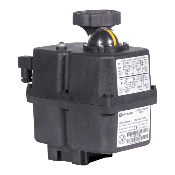
2.- LOCAL VISUAL POSITION INDICATOR
LOCAL VISUAL POSITION INDICATOR
LOCAL VISUAL POSITION INDICATOR:
LOCAL VISUAL POSITION INDICATOR
All ECP
ECP-Series actuators are supplied with a local visual position indicator compris
actuators are supplied with a local visual position indicator compris
actuators are supplied with a local visual position indicator compris
actuators are supplied with a local visual position indicator compris
actuators are supplied with a local visual position indicator comprising
actuators are supplied with a local visual position indicator compris
insert that shows
insert that shows
both the position and direction of rotation. (see Fig. 5)
both the position and direction of rotation.
both the position and direction of rotation.
both the position and direction of rotation.
The opened and close
The open
closed positions have the following logos moulded in to the top cover OPEN
positions have the following logos moulded in to the top cover OPEN
positions have the following logos moulded in to the top cover OPEN
positions have the following logos moulded in to the top cover OPEN
positions have the following logos moulded in to the top cover OPENED 90 and
positions have the following logos moulded in to the top cover OPEN
CLOSE
CLOSED 0.
Opening =
Opening =
Closing =
Closing =
Hayward
Flow Control
ECP-
-SERIES ON/OFF
ON/OFF INSTALLATION
ORE CONNECTING THE ACTUATOR. DAMA
ORE CONNECTING THE ACTUATOR
WARRANTY.
use of live electricity. It is recom
pumps).
that the voltage to be ap
that the voltage to be applied to the actuator is within
lied to the actuator is within the range shown on the identification label.
lied to the actuator is within
and minimum requirements of the DIN plugs to maintain wate
requirements of the DIN plugs to maintain water tightness.
requirements of the DIN plugs to maintain wate
requirements of the DIN plugs to maintain wate
requirements of the DIN plugs to maintain wate
NEUTRAL o (-)
NEUTR
PIN 1
PIN 1
THE TOP FLAT PIN IS THE GROUND
FLAT PIN IS THE GROUND CONNECTION
FLAT PIN IS THE GROUND
PIN1
COMMON
COMMON
contact the vendor.
contact the vendor.
parallel wiring multiple actuators together
parallel wiring multiple actuators together
parallel wiring multiple actuators together
parallel wiring multiple actuators together
by this installation error will
by this installation error will void warranty.
screw. Do not overtight
Do not overtight the screw when assembling.
the screw when assembling.
the screw when assembling.
:
www.haywa
INSTALLATION INSTRUC
INSTRUCTIONS
DAMAGE CAUSED BY NON COMPLIANCE TO THESE
GE CAUSED BY NON COMPLIANCE TO THESE
GE CAUSED BY NON COMPLIANCE TO THESE
GE CAUSED BY NON COMPLIANCE TO THESE
city. It is recommended that only qualified electric
ended that only qualified electric
ended that only qualified electricians install
ended that only qualified electric
the range shown on the identification label.
the range shown on the identification label.
the range shown on the identification label.
the range shown on the identification label.
DIN-43650 ISO 4400 &
DIN
Model
Model
diameter
ECP2 – ECP8
ECP2
5mm
PHASE o (+)
ASE o (+)
ROTATION
ROTATION
PIN 2
CLOSE
CLOSE
PIN 3
OPEN
OPEN
CONNECTION
PIN2
PIN 3
PIN 3
CLOSED
OPEN
OPEN
POSITION
POSITION
POSITION
POSITION
CONFIRMATION
CONFIRMATION
CONFIRMATION
CONFIRMATION
warranty. The DIN plugs are fixed to their respective bases on
The DIN plugs are fixed to their respective bases on
The DIN plugs are fixed to their respective bases on
The DIN plugs are fixed to their respective bases on
The DIN plugs are fixed to their respective bases on
condensation heater that is automatically actived wh
condensation heater that is automatically actived when
condensation heater that is automatically actived wh
condensation heater that is automatically actived wh
power supply.
supply.
ing of a black base with a yello
of a black base with a yellow
of a black base with a yello
5)
ardflowcontrol.co
om
tightness.
BLACK (SMALL
SMALL)
GREY (LARGE)
CONNECTOR
CONNECTO
CONNECTOR
CONNECTOR
43650 ISO 4400 &
DIN
DIN-43650 ISO 4400
43650 ISO 4400
C192
C192
min
max
min
diameter
di
diameter
di
6mm
8mm
actuator. Failure to do so could allow
Failure to do so could allow
Failure to do so could allow
90 and
1-888-H
HAY-INDL (1-888
ECPIOM Rev
install or
(LARGE)
& C183
& C183
max
dia
ameter
10.5mm
10.5mm
888-429-4635)
ev B 12/3/14
Advertisement
Table of Contents

Related Manuals for Hayward ECP Series


Summary of Contents for Hayward ECP Series
- Page 1 OPENED 90 and 90 and CLOSE CLOSED 0. Opening = Opening = Closing = Closing = Hayward Flow Control www.haywa ardflowcontrol.co 1-888-H HAY-INDL (1-888 888-429-4635) ECPIOM Rev ev B 12/3/14...
- Page 2 Battery protection. Danger - The battery needs recharging. BSR disabled (applies only 200 mSeg. 1010 1000 0000 0000 to units with optional battery back-up). Hayward Flow Control www.haywardflowcontrol.com 1-888-HAY-INDL (1-888-429-4635) ECPIOM Rev B 12/3/14...
Need help?
Do you have a question about the ECP Series and is the answer not in the manual?
Questions and answers