Sign In
Upload
Download
Table of Contents
Contents
Add to my manuals
Delete from my manuals
Share
URL of this page:
HTML Link:
Bookmark this page
Add
Manual will be automatically added to "My Manuals"
Print this page
×
Bookmark added
×
Added to my manuals
Manuals
Brands
Hayward Manuals
Controller
ECP3 Series
Installation, operation and maintenance instructions
Hayward ECP3 Series Installation, Operation And Maintenance Instructions
Hide thumbs
1
2
Table Of Contents
3
4
5
6
7
8
9
10
11
12
13
14
15
16
17
18
19
20
21
22
23
page
of
23
Go
/
23
Contents
Table of Contents
Troubleshooting
Bookmarks
Table of Contents
Important Safety Instructions
Table of Contents
ECP Series Operational Concepts
Technical Information
Wire Sizing Chart
ECP Component Identification
Quick Reference Guide
Actuator Handling and Installation
Shipping and Handling
Installation Notes
Product Mounting and Setup
Operational Status LED
On/Off Control
Wiring Diagram
Calibration and Commissioning
On/Off Control
Proportional Controller
PC Option - External Self-Adjustment
Wiring Diagram
PC Option - Controller Setup
Calibration and Commissioning
Proportional Control
BB Battery Backup
Setup for Fail CW/CCW
Disassembly / Assembly
Adjusting CW End of Travel
Adjusting CCW End of Travel
Troubleshooting
Mechanical Data
Model: ECP3
Model: ECP5
Model: ECP8
Internal Component Details
Ecp3, Ecp5 & Ecp8
Motor Power Consumption
Advertisement
Quick Links
1
Technical Information
2
Installation Notes
3
Operational Status Led
4
Wiring Diagram
5
Troubleshooting
6
Model: Ecp3
Download this manual
INSTALLATION, OPERATION AND
MAINTENANCE INSTRUCTIONS
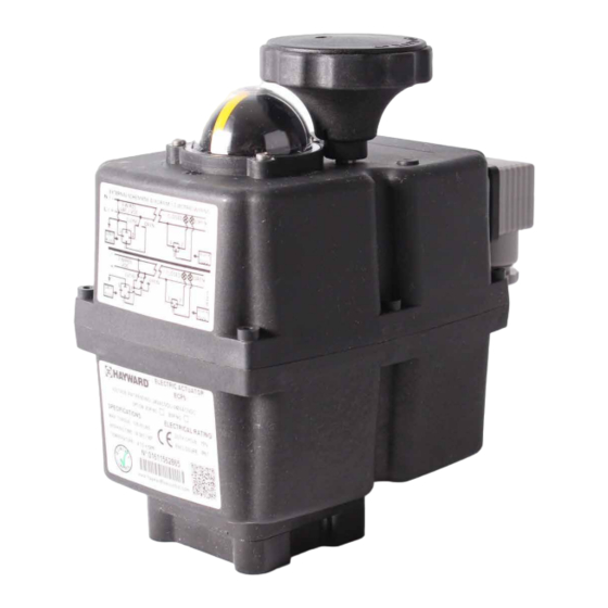
ECP3, ECP5, ECP8 Series Actuators
TO PREVENT POTENTIAL INJURY OR DAMAGE TO PROPERTY, READ THIS MANUAL CAREFULLY AND COMPLETELY.
Table of
Contents
Previous
Page
Next
Page
1
2
3
4
5
Advertisement
Table of Contents
Need help?
Do you have a question about the ECP3 Series and is the answer not in the manual?
Ask a question
Questions and answers
Related Manuals for Hayward ECP3 Series
Controller Hayward ECP Series On/Off Installation Instructions
(2 pages)
Controller Hayward ECP5 Series Installation, Operation And Maintenance Instructions
(23 pages)
Controller Hayward EAU129 Series Installation, Operation And Maintenance Instructions
(6 pages)
Controller Hayward Aqua Plus Operation Manual
Model: pl-plus-16v operation (26 pages)
Controller Hayward E-Command 4 Operation Manual
Ecommand 4 series controller (32 pages)
Controller Hayward Aqua Solar GL-235 Operation And Installation Manual
Electronic solar control (6 pages)
Controller Hayward Aqua Plus Operation Manual
Model: pl-plus operation (20 pages)
Controller Hayward ColorLogic LKCUS1100 Owner's Manual
Light controller (2 pages)
Controller Hayward CAT-2000 Owner's Manual
Automated controller (28 pages)
Controller Hayward HCC 4000 Owner's Manual
Water quality controller (36 pages)
Controller Hayward ProChem Double Owner's Manual
(241 pages)
Controller Hayward CAT 5500 Owner's Manual
Water quality controller (36 pages)
Controller Hayward CAT 2000 W3CATPP2000 Owner's Manual
Automated controller (28 pages)
Controller Hayward GVA-24 Installation Manual
Valve actuator (16 pages)
Controller Hayward HCC 2000 Owner's Manual
Automated controller (24 pages)
Controller Hayward HRSN2 Series Installation, Operation And Maintenance Instructions
(36 pages)
This manual is also suitable for:
Ecp5 series
Ecp8 series
Table of Contents
Print
Rename the bookmark
Delete bookmark?
Delete from my manuals?
Login
Sign In
OR
Sign in with Facebook
Sign in with Google
Upload manual
Upload from disk
Upload from URL


Need help?
Do you have a question about the ECP3 Series and is the answer not in the manual?
Questions and answers