Table of Contents
Advertisement
Quick Links
Advertisement
Table of Contents

Related Manuals for RTimes RTSO-1001


Summary of Contents for RTimes RTSO-1001
- Page 1 RTSO-1001 Reference Manual Realtimes Beijing Technology Co., LTD. Fax:+86 010-84284669 / 84280996 / 84278927 Email: info@realtimes.cn Web Page: http://www.realtimes.cn Address: 9th Floor, Block B, 20th Heping Xiyuan, Pingxi Street, Chaoyang District, Beijing 100013,P.R.China...
- Page 2 Revision History Editor Revision Date Reason for change Applicable hardware version V1.0 2019-10 Initial release V1.0 V1.1 2019-11 Replace the picture V1.1 V1.2 2020-02 Update relevant information V1.1 RTSO-1001 Reference Manual V1.2...
- Page 3 Therefore, it is recommended to observe anti-static safety precautions when handling any circuit board component (including RTSO-1001). Anti-static safety protection measures include, but are not limited to the following: a) The smart box should be placed in an anti-static bag during transportation and storage, and then the board should not be taken out during installation and deployment.
- Page 4 3) Burn in verification of all BSP support packages provided by the company; 4) The company released burn environment construction, entry-level use. ; 5) Various peripheral module drivers released by the company; 6) The company's product fault diagnosis and after-sales maintenance services; RTSO-1001 Reference Manual V1.2...
- Page 5 Updates of subsequent documents, BSP, driver files and other official account will be updated in time. We will pay close attention to our developments in order to ensure that your information is up to date. We will push through WeChat public. RTSO-1001 Reference Manual V1.2...
-
Page 6: Table Of Contents
INTERFACE 4.10 F ..............................18 UNCTION 4.11 SD C ..............................19 ARD SLOT 4.12 P ...............................19 OWER PORT 4.14 N ............................20 ETWORK INTERFACE 5 HARDWARE UPDATE HISTORY..........................21 6 PRODUCT SIZE................................22 7 DRIVE..................................22 TERMS OF WARRANTY..............................23 RTSO-1001 Reference Manual V1.2... -
Page 7: Abstract
Small group area. Mainly aimed at the rapid development of artificial intelligence market in recent years, such as unmanned aerial vehicle, automatic driving system, etc., with a relatively wide range Broad application prospects. Rtso-1001 is the industrial-grade loading board for Xavier, operating temperature -40℃ -- +80℃, low power consumption, safety level High, can meet a variety of harsh conditions. -
Page 8: Ordering Information
(optional) (four-channel SDI Video input) ME909S-821(optional) mini-PCIe Full netcom 4G module Order online https://shop340963258.taobao.com https://mall.jd.com/index-824786.html 1.3 Wiring package configuration Out of Cables packing orders for RTSO-1001 are: RTSO-1001-Cables. Contains the following components: Numb Functional Component TYPE-C turn TYPE-A Convert the Type-a interface to the Type-a interface 3x3.3V UART/6x3.3V GPIO,1x3.3V SPI/4x3.3V... -
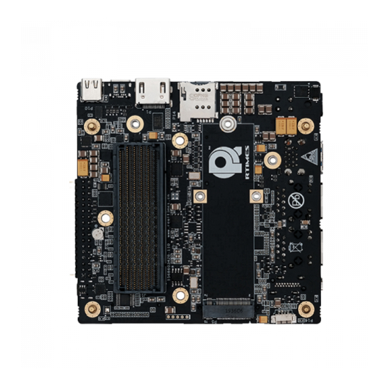
Page 9: Connector Locations
Realtimes Beijing Technology Co.,LTD www.realtimes.cn/en/index.html 2 Connector Locations RTSO-1001 Reference Manual V1.2... -
Page 10: Functional Connector
POWER button is used for system shutdown and POWER on after soft shutdown RECOVERY RECOVERY button is used to put the core module into recovery mode 2.3 2.3 indicator light Indication sign 功能描述 MCU LED 闪烁-核心正常启动 POWER IN LED 常亮-电源 CARRIER POWER LED 常亮-载板正常启动 RTSO-1001 Reference Manual V1.2... -
Page 11: Installation And Use
The steps to enter the Recovery mode are as follows: Turn off the system power supply. Use USB cable to connect RTSO-1001's USB port (P10) with Jetson to develop the host USB port. Press the RECOVERY button without releasing it to power the system. The power supply should be maintained for more than 3 seconds, and then the RECOVERY button will be released. -
Page 12: Connectors Description
TACH Pin 1: Mark in the red box of the picture on the right. 4.3 Micro SIM card slot Function Micro SIM card slot Marking Type Micro SIM Pin define Signal Signal UIM_PWR UIM_RESET UIM_CLK UIM_DATA RTSO-1001 Reference Manual V1.2... - Page 13 M.2 interface P5/P6 Marking Key M Type Pin define Signal Signal PCIE_RX3_N PCIE_RX3_P PCIE_TX3_N PCIE_TX3_P PCIE_RX2_N PCIE_RX2_P PCIE_TX2_N PCIE_TX2_P PCIE_RX1_N PCIE_RX1_P PCIE_TX1_N PCIE_TX1_P PCIE_CLK PCIE_RX0_N PCIE_DATA PCIE_RX0_P ALERT PCIE_TX0_N PCIE_TX0_P PERST# CLKREQ# PCIE_CLK_N PEWAKE# PCIE_CLK_P SUSCLK(32KHZ) RTSO-1001 Reference Manual V1.2...
-
Page 14: Usb Type-Ainterface
Hot Plug Detect 4.6 USB TYPE- C interface USB interface Function P10/P11 Marking Type TYPE-C Pin define Signal Signal GND_A1 GND_B1 TX1_P TX2_P TX1_N TX2_N VBUS_A4 VBUS_B4 D1_P D2_P D1_N D2_N SBU1 SUB2 VBUS_A9 VBUS_B9 RX2_N RX1_N RTSO-1001 Reference Manual V1.2... -
Page 15: Mini Pcie Slot
Mini PCIE slot Marking Type Mini PCIE Pin define Signal Signal 3.3V WAKE 1.5V PCIE_CLKREQ UIM_PWR UIM_DATA PCIE_C4_CLK- UIM_CLK PCIE_C4_CLK+ UIM_RESET W_DISABLE PCIE_REST PCIE_C4_RX- 3.3V PCIE_C4_RX+ 1.5V I2C_GP5_CLK PCIE_C4_TX- I2C_GP5_DAT PCIE_C4_TX+ USB3_DN USB3_DP VCC_3V3_PCIE VCC_3V3_PCIE 1.5V 3.3V RTSO-1001 Reference Manual V1.2... -
Page 16: Camera Interface
CSI_0_D1_N CSI_1_D1_N CSI_2_D0_P CSI_3_D0_P CSI_2_D0_N CSI_3_D0_N CSI_2_CLK_P CSI_3_CLK_P CSI_2_CLK_N CSI_3_CLK_N CSI_2_D1_P CSI_3_D1_P CSI_2_D1_N CSI_3_D1_N CSI_4_D0_P CSI_6_D0_P CSI_4_D0_N CSI_6_D0_N CSI_6_CLK_P CSI_4_CLK_P CSI_4_CLK_N CSI_6_CLK_N CSI_4_D1_P CSI_6_D1_P CSI_4_D1_N CSI_6_D1_N CSI_5_D0_P CSI_7_D0_P CSI_5_D0_N CSI_7_D0_N CSI_5_CLK_P CSI_7_CLK_P CSI_7_CLK_N CSI_5_CLK_N CSI_5_D1_P CSI_7_D1_P RTSO-1001 Reference Manual V1.2... -
Page 17: Key Einterface
GPIO15_CAM1_PWDN CAM0_MCLK02 GPIO16_CAM1_RST CAM0_PWDN CAM2_MCLK04 CAM0_RST_BUFFER 1.8V I2C_GP4_CLK I2C_GP4_DAT 3.3V 3.3V 3.3V GPIO25_VDD_SYS_EN 3.3V 4.9 M.2 key E interface Function Marking Key E Type Pin define Signal Signal 3.3V USB2_D+ 3.3V USB2_D- LED_1# PCM_CLK/I2S_2 SCK PCM_SYNC/I2S2_WS RTSO-1001 Reference Manual V1.2... - Page 18 Realtimes Beijing Technology Co.,LTD www.realtimes.cn/en/index.html PCM_OUT/I2S2_SD_OU PCM_IN/I2S2_SD_IN LED_2# UART5_WAKE# M2_EN UART5_TXD M2_WAKE_AP UART5_RXD UART5_RTS PERP0 UART5_CTS PERNO VENOOR_DEFINED PETP0 PETN0 REFCLKN0 REFCLKP0 SUSCLK_32KHZ PERST0# CLKREQ0# W_DISABLE2# PEWAKE0# W_DISABLE1# I2C_GP2_DATA RESERVED/PERP1 I2C_GP2_CLK RESERVED/PERN1 ALERT# 3.3V 3.3V RTSO-1001 Reference Manual V1.2...
-
Page 19: Function Pin
The mapping file in the /dev directory corresponding to UART1 and UART2 is ttyTHS0, ttyTHS1, and UART3 is the debugging port The mapping Numbers of GPIO04, GPIO05, GPIO20 and GPIO21 in the system are 288, 289, 290 and 291 respectively RTSO-1001 Reference Manual V1.2... -
Page 20: Sd Card Slot
DATA0 CD/DATA3 DATA2 C_DETECT 4.12 Power port Function Power port Marking Type Type of big Pin define Signal Signal Pin 1 position: as shown in the right figure Input voltage range:+9v~+20v Cable connection is strictly prohibited! RTSO-1001 Reference Manual V1.2... -
Page 21: Network Interface
Signal VBUS USB 2.0 D- USB 2.0 D+ SSRX- SSRX+ SSTX- SSTX+ 4.14 Network interface Function Ethernet connector P8/P9 Marking RJ45 network interface Type Pin define Signal Signal TP0+ TP0- TP1+ TP2+ TP2- TP1- TP3+ TP3- RTSO-1001 Reference Manual V1.2... -
Page 22: Hardware Update History
Function USB2.0 connector Marking Micro-B Type Pin define Signal Signal VBUS USB 2.0 D- USB 2.0 D+ 5 Hardware update history RTSO-1001 Board hardware update history Versions Update Description V1.0 Initial version V1.1 Hardware circuit optimization RTSO-1001 Reference Manual V1.2... -
Page 23: Product Size
6 Product size 7 Drive RTSO-1001 boards work on systems that are burned using the official original NVIDIA Linux For Tegra (L4T). HDMI, Gigabit Ethernet, USB2.0, serial port, GPIO, SD card, I2C bus, fan interface, can be supported. RTSO-1001 onboard interface full support, need to load the supporting driver patch. -
Page 24: Terms Of Warranty
Rev.C 6/2020 RTSO-1001 Reference Manual V1.2... - Page 25 Realtimes Beijing Technology Co.,LTD www.realtimes.cn/en/index.html RTSO-1001 Reference Manual V1.2...
Need help?
Do you have a question about the RTSO-1001 and is the answer not in the manual?
Questions and answers