
Related Manuals for DGC ZM-DGC900


Summary of Contents for DGC ZM-DGC900
- Page 1 BGA Rework Station ZM-DGC900 SOFTWARE SOLUTIONS Address: Office 12D Fuxin Building , 318 Fuhua Road , 558000, Shenzhen, China Telephone: (86)0755-88360496 Fax:(86)0755-83292149 Http : //www.dragongroupchina.com...
-
Page 2: Table Of Contents
Contents A. Company Profile B. BGA Rework Station C. Installation D. Safety Cautions E. Introduction of Structure F. Operation Steps G. PLC (Programmable logic Controller) H. Curve Program Controller I. Related information J. Tips for operation Appendix: Packing list. -
Page 3: Company Profile
A. Company Profile DGC as quality control specialist in China started operations since 2007, with the Union of intelligent human resources from China and Overseas, it has since then paved the way for Chinese brand best products in outside markets, also promote and develop strategies for different products according to languages and needs have been basic in DGC objectives. - Page 4 (6)The tension between solder points produces good self-centration effect in solder- reflow, allowing 5% error of patch precision. (7)Compatible with original SMT mount technology and machines. The original screen printer machine, mounter and solder-reflow machine all can be used. The comparison between BGA and QFP is shown in Table 1.
- Page 5 point is that the welding spots can still be welded on the pad. The ideal situation is no poor welding. Poor welding may be caused by pollution or the uneven distribution of flux paste. What's more, warped PCB may also lead to poor welding. Open-circuit welding spot may exist, too.
-
Page 6: Installation
the space around CSP is very small. d. Lay on BGA Flux Paste Laying solder paste on the PCB has important influence on the result of BGA Rework. It is convenient to lay solder paste on the PCB by selecting mould matched with BGA. -
Page 7: Safety Cautions
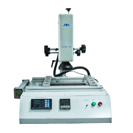
h. Leave a space of 30cm or more behind the rework station for the upper part to move and rotate. 2. Power supply: a. Use a power supply with little fluctuations in voltage. b. Fluctuation: 220V±10 c. Frequency fluctuation: 50Hz±3 D. - Page 8 08 横流风扇 01 上部加热Y轴调节手柄 02 上部加热Z轴调节手柄 09 上部温控器 03 发热器组 10 电脑连接口 04 发热器射灯 05 下部测温器 11 下部温控器 06 PCB托板 12 冷却开关 13 启动 07 下部发热器板 14 停止 Introduction of host labels: 1. Top heater temp control 2. Bottom heater temp control 3.
-
Page 9: Operation Steps
5. This machine can be connected to a computer to be controlled more conveniently with a built-in PC serial port and a proprietary software attached to it. 6. After finishing desoldering & soldering, there is an alarming. The machine is equipped with a vacuum suction pen to facilitate the removing of BGA after desoldering. - Page 10 a. Panel introduction Model: PC410 sectional type temperature controller Set Procedure first turn on the switch 1) the NO. Of the group set Choose the position to keep the temperature(can keep 10 groups temperature graphs) Press the PTN to set the NO. Of group from one of (1,2,3,4,5,..0) and the temperature graphs,(choose NO.X from ten groups,take NO.1 group as an example) D I S P S E L E...
- Page 11 to enter the next step. D I S P S E L E T I M E C O M S E T 3 . 0 0 P R O G M A N R U N A U T O H A N D P R O G R U N...
- Page 12 D I S P S E L E C O M T I M E S E T 3 . 0 0 P R O G M A N R U N A U T O H A N D P R O G R U N A L 1...
- Page 13 9)Enter the third section:constant temperature set, press UP/DOWN to modify.Press the PAR to define. D I S P S E L E T I M E C O M S E T 2 1 0 P R O G M A N R U N A U T O P R O G...
- Page 14 D I S P S E L E T I M E C O M S E T 2 2 5 P R O G M A N R U N A U T O P R O G H A N D R U N A L 1 P T N...
- Page 15 (16)Enter the fifth section: constant temperature time set, press UP/DOWN to modify. Press the PAR to define. D I S P S E L E C O M T I M E S E T P R O G M A N R U N A U T O P R O G...
- Page 16 b. Panel display When we turn on the meter, the upper screen displays the basic model, the lower shows the version of the software (for the customized meter, the customer should pay special attention to the software version, to facilitate future order). Three seconds after, the upper screen displays measurements (PV), the lower screen displays settings (SV).
- Page 17 When the meter is set to constant temperature controller, the two display windows: PTN and STEP, PROFILE, RUN, these four lights were off. OUT1 is used to indicate the working state of output 1. It is on when there is output. OUT2 is used to indicate the working state of output 2, It is on when there is output.
- Page 18 parameter code; the lower screen shows the value of the parameters. Then press ▲or ▼button to modify the value of the parameter. When finished, press the button PAR, meters will show next code and the value of the parameters in order. Revised data will be saved in the memory of the instrument.
- Page 19 Heating period No display when Ctrl is set at Hc と 0.1~240.0 s ON/OFF Cooling period Display when heating/cooling cc と 0.1~240.0 s Configuration 0~9999 password Don't change the settings during PID self-setting, because one change leads to one restart, then PID time is prolonged.
- Page 20 Output signals J Sensor J と C K Sensor [R と C E Sensor E と C R Sensor r と c S Sensor s と c B Sensor b と c T Sensor とと c Pt100 platinum resistor r と d Pt100 platinum resistor (with decimal) Cu50 copper resistor...
- Page 21 RL02 Second alarming output Action (suction) RL01 First alarming LoRL Under bottom- When the OP2 is the line alarming second alarming, AL02 (AL1) Over display on the screen. ndRo deviation-line RL02 Second alarming Pout alarming (AL2) Under bottom deviation-line alarming Within deviation alarming...
- Page 22 Only if the system is heating or cooling, rEL.C displays. In the process of PID self-setting, the system can only set ProP, ln とと and dEr と. The cooling parameter rEL.C should be set by hand. If the adjust method is set at positioning adjustment, ProP is the difference of positioning adjustment.
-
Page 23: Curve Program Controller
Switching positions time rannge 1M~99H99M 1S~99M99S 0.01S~99.99S (3). Setting figures increase (4). Setting figures decrease (5). Setting shift (6). SET: process set Note: DH48S showing time is the range of electrical continuing (set by using the coding switch of panel) b. - Page 24 d1=0 Setpoint Setpoint Start value= Start value= measured value measured value time time Setpoint Setpoint time time Start value= measured value Start value= measured value a. Pn0:saved curve program(0~4groups); r1:the slope of Curve 1;End;StEP;0.01~99.9°C/min; Set the slope at End:When the curve program goes to this section, it stops. Set the slope at StEP:when the curve program goes to this section,the program skip this section and goes to next flat section.
- Page 25 When the meter displays RUN, the RAMP is on. When the meter displays HOLD or Hb, the RAMP blinks. Note: When the CTrl is set at rSP, and the curve goes through the slope, the RAMP is on. (2)display while running When the meter displays RUN, Hb or HOLD, press PAR.
-
Page 27: Related Information
I. Related information 1. How to deal with the Voids produced by the lead BGA in lead-free soldering? As the development of the lead-free technology, more and more SMT processing enterprises come across the problem of Voids in production. Many companies try to avoid using lead BGA in lead-free soldering technology. Because the melting point of lead soldering balls is lower than lead-free tin paste. - Page 28 analysis of material temperature. The convection rework station which can save many temperature curves is directed by the approximate situation of PCB heating. The more precise method is to connect a K sensor to the PCB to detect the temperature. What’s more, the final form of process control is to detect the welding points in the process, or to detect the reflow points.
- Page 29 The Full component is entirely covered by the beam, and BGA can be heated evenly. In the Case of the ZM-DGC 900, You can chose a diameter of the heat you want to apply according to the size of the IC Component you will work on.
-
Page 30: Tips For Operation
J. Tips for operation 1. After turn on the head power switch, check whether the upper hot-air nozzle gives out cool breeze. If not, never start the machine, or the upper heater may be burnt. 2. Set different temperature curves for different BGA. The temperature should not be higher than . -
Page 31: Appendix: Packing List
To meet the fast-increasing demand of BGA circuit assembly, the manufacture companies need to choose safer, faster and more convenient assembly and rework technology. packing list Appendix: Order Name Specification Unit Note BGA Rework ZM-DGC900 (electric cabinet) Station Install program Software Vacuum sucker Temperature sensor Data access Power cable Instruction...
Need help?
Do you have a question about the ZM-DGC900 and is the answer not in the manual?
Questions and answers