GMI PS500 User Handbook Manual
Hide thumbs
Also See for PS500:
- User handbook manual (70 pages) ,
- User handbook manual (127 pages) ,
- User training (26 pages)
Table of Contents
Advertisement
Advertisement
Table of Contents

Related Manuals for GMI PS500


Summary of Contents for GMI PS500
- Page 1 Gas Measurement Instruments Ltd User Handbook...
- Page 2 Issue 3 28/01/16 Part Number: 61095 GMI welcomes comments on all our publications. Your comments can be of great value in helping us to improve our customer publications. Please send any comments that you have to customerservice@gmiuk.com © 2015 Gas Measurement Instruments Ltd...
-
Page 3: Copyright
SOFTWARE Software supplied, may only be used with the PS500 and may not be copied without the written permission of GMI. Reproduction or disassembly of such software is prohibited. Ownership of software is not transferable and GMI does not guarantee that the software operation will be error free or meet the customer’s requirements. -
Page 4: Areas Of Use
There are no special precautions to be taken when the instrument is in transit. WARRANTY The PS500 instrument has a warranty against faulty goods or workmanship of 2 years. Consumable parts are not included in this. These are covered under GMI... -
Page 5: Table Of Contents
CONTENTS COPYRIGHT ..............iii LIABILITY ...............iii MODIFICATION NOTICES..........iii SOFTWARE ..............iii DISPOSAL ADVICE ............iii SAFETY................iii AREAS OF USE .............iv STORAGE, HANDLING AND TRANSIT ......iv WARRANTY ..............iv INTRODUCTION ........... 1-1 1.1 GENERAL DESCRIPTION ........1-1 1.2 FEATURES............1-3 1.3 DATA LOGGING ........... 1-4 1.3.1 Viewing Data Logged Readings .... - Page 6 USER HANDBOOK OPERATION ............2-1 2.1 OPERATING PROCEDURE......... 2-1 2.2 SWITCHING THE INSTRUMENT ON ....2-2 2.2.1 Instrument Identification ....... 2-3 2.2.2 Time and Date ..........2-3 2.2.3 Calibration Due Date ........2-4 2.2.4 Select Calibration Gas........2-5 2.2.5 Select VOC Target Gas ........ 2-6 2.2.6 Sensor Confirmation Check ......
- Page 7 CONTENTS 3.1.2 Over-Range Flammable Gas Alarm Function .................. 3-1 3.1.3 Oxygen (O ) Alarm Limits ......3-1 3.1.4 Toxic Alarm Limits ......... 3-2 3.2 ACKNOWLEDGE GAS ALARMS ......3-4 3.3 HIGH FLAMMABLE GAS OVER-RANGE ALARM ..................3-5 3.4 FAULT ALARMS ........... 3-7 3.4.1 Low Battery ..........
- Page 8 5.2 CALIBRATION VALIDITY ........5-2 ACCESSORIES............. 6-1 ADDITIONAL INFORMATION ....... 7-1 7.1 TRAINING ............7-1 7.2 GMI WEBSITE ............. 7-1 PID SENSORS ............A-1 What is a Volatile Organic Compound (VOC)? ..A-1 How can a VOC be measured?......A-1 Maintenance and Cleaning of PID sensors ....A-1 Response Factors ..........A-2...
-
Page 9: Introduction
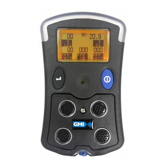
INTRODUCTION 1.1 GENERAL DESCRIPTION The PS500 combines quality and ruggedness in a user friendly, portable gas detector. Small and lightweight, it is suitably certified to recognised International Standards. Fig. 1.1 PS500 Instrument The PS500 is used for confined space applications, for example, in sewers, underground piping or within tanks, and other personal monitoring applications. - Page 10 USER HANDBOOK Up to five gases can be monitored from the following list: • 0 to 100% LEL Hydrocarbons • 0 to 25% Oxygen (O • 0 to 100 ppm Hydrogen Sulphide (H • 0 to 1000 ppm Carbon Monoxide (CO) •...
-
Page 11: Features
INTRODUCTION The instrument display identifies the gas(es) the instrument is monitoring. A five gas instrument display is shown in Fig. 1.2: Fig. 1.2 (5-Gas) Display Example Note: This Handbook describes the operation of a typical five gas instrument. Configurable options are detailed in italic text. -
Page 12: Data Logging
1.3.1 Viewing Data Logged Readings Data logged readings can be downloaded from the instrument, to a PC, using GMI software and communication adaptor. at GMI for further details. Contact our Sales Department 1.4 HYDROPHOBIC FILTER(S) -
Page 13: Certification
INTRODUCTION 1.7 CERTIFICATION The PS500 instrument is certified as follows: II 1 G EEx ia IIB T3 ATEX II 2 G EEx ia d IIC T3 ATEX II 2 G EEx ia d IIC T4 ATEX 1.7.1 Identification of Symbols Certification No. -
Page 14: Performance
To prevent ignition of flammable or combustible atmospheres, disconnect power (i.e. remove battery pack) before servicing. WARNING Replace battery pack only with GMI Part No. 66701, 66702 or 66703. WARNING Do not mix new batteries with used batteries, or mix batteries... -
Page 15: Operation
OPERATION 2.1 OPERATING PROCEDURE Before use, check the following: • The instrument is clean and in good condition. • The battery pack is in good condition, fully charged and fitted correctly. The hydrophobic filter is clean and in good condition. •... -
Page 16: Switching The Instrument On
LEFT BUTTON RIGHT BUTTON Fig. 2.1 PS500 Button Operation The instrument begins its warm-up routine, a countdown timer appears in the top centre of the display. Note: The display backlight illuminates during warm- up. -
Page 17: Instrument Identification
OPERATION 2.2.1 Instrument Identification During warm-up, the instrument display identifies the model, serial number, software version, datalogging option and battery status information as shown in Fig. 2.2. Fig. 2.2 Instrument Identification 2.2.2 Time and Date The time and date is displayed on the screen during warm-up, as shown in Fig. -
Page 18: Calibration Due Date
USER HANDBOOK 2.2.3 Calibration Due Date The calibration due date appears on the display, as shown in Fig. 2.4. A configurable option is available not to display this screen. Fig. 2.4 Calibration Due Date If the Calibration Due Date has expired, the audible and visual alarms activate and Fig. -
Page 19: Select Calibration Gas
OPERATION 2.2.4 Select Calibration Gas This configurable option is available to allow the user to select a different flammable gas from that which was originally used to calibrate the instrument. When this option is displayed, as shown in Fig. 2.6, the gas that was originally used to calibrate the instrument is identified between two arrowheads. -
Page 20: Select Voc Target Gas
USER HANDBOOK 2.2.5 Select VOC Target Gas This configurable option is available to allow the user to select a different VOC gas from that which was originally used to calibrate the instrument. When this option is displayed, as shown in Fig. 2.7, the VOC gas that was originally used to calibrate the instrument is identified between two arrowheads. -
Page 21: Sensor Confirmation Check
OPERATION 2.2.6 Sensor Confirmation Check The symbol appears above each sensor type to confirm that the sensor has been recognised and is being zeroed. When sensors are zeroed correctly, a symbol appears above each sensor, as shown in Fig 2.8. Followed by Fig. - Page 22 USER HANDBOOK Fig. 2.9 Failed Sensor To acknowledge the alarm, press the button. This will clear the audible / visual alarms and display a flashing spanner symbol, *alternating with the faulty sensor zero reading (*LEL sensor only), as shown in Fig. 2.10. Alternating with Fig.
-
Page 23: Normal Operating Display
OPERATION A configurable option is available to force the user to switch the instrument off if a zero fault is detected, as shown in Fig. 2.11: Fig. 2.11 Switch OFF Note: If a sensor fault is detected during normal operation, an audible / visual alarm is activated immediately and a spanner symbol is shown above the faulty sensor type. -
Page 24: Switching The Display Backlight On / Off
USER HANDBOOK 2.3 SWITCHING THE DISPLAY BACKLIGHT ON / OFF Press the button once to switch the display backlight on. It remains on for 20 seconds and then automatically switches off. 2.4 VIEWING THE MAXIMUM AND MINIMUM RECORDED VALUES SINCE SWITCH ON The instrument records the maximum and minimum gas values for each sensor, since switch-on. - Page 25 OPERATION The example shown in Fig. 2.14 illustrates the maximum gas values stored. Fig. 2.14 Maximum Gas Values Press the button again to view the minimum gas values stored in the instrument. Note: This screen is only displayed when an Oxygen sensor is fitted in the instrument.
-
Page 26: Manual Data Log
USER HANDBOOK 2.5 MANUAL DATA LOG A manual data log can be stored at any time during operation, by a press of the button. Fig. 2.16 illustrates a manual data log being stored. Fig. 2.16 Manual Data log 2.6 SELF TEST The instrument has the ability to perform a self test at any time during operation. -
Page 27: Voc Target Gas Selection
OPERATION 2.7 VOC TARGET GAS SELECTION This configurable option allows the user to select a different VOC gas from that which was originally used to calibrate the instrument. To select a different VOC gas, press and hold for 5 seconds until the VOC target gas selection is displayed, as shown in Fig. -
Page 28: Alarms Reset Or Acknowledge
Non-Latching - the audible and visual alarms will reset automatically when the reading returns within the pre-set alarm limits. Caution: The PS500 can be supplied with a flammable gas sensor. This sensor is designed for use in concentrations of gas not exceeding the Lower Explosive Limit (LEL). - Page 29 Low Pitch Tone All Slow Flashing (Pumped Instr. Only) Calibration Expired Low Pitch Tone All Slow Flashing Service Required Low Pitch Tone All Slow Flashing Over Range (LEL) Continuous Wail All Fast Flashing N/A = Not Applicable Table 2.1 PS500 Alarms 2-15...
-
Page 30: Confidence Signal
USER HANDBOOK 2.8.1 Confidence Signal During normal operation, the instrument sounds a confidence beep and illuminates the green visual alarm briefly every 15 seconds. This function is configurable and informs the user that the instrument is operating correctly. 2.9 SWITCHING THE INSTRUMENT OFF Press and hold both the button and the button together... -
Page 31: Remote Sampling (With Pump Option)
OPERATION 2.10 REMOTE SAMPLING (with pump option) Warning: When making VOC measurements, only use the Viton sample line as other sample lines may absorb VOC’s resulting in incorrect readings. Remote sensing is performed with the internal electric pump (optional), or by the hand aspirator for non-reactive gases, using the sample connector at the bottom of the instrument and sample tubing supplied with your instrument. -
Page 32: Assisted Diffusion Option
OFF. A further press and hold of the button re-sets the pump to run at low speed. Note*: GMI recommend that pumped instruments, measuring reactive gases, use assisted diffusion mode in preference to diffusion mode. 2-18... -
Page 33: Alarms
ALARMS 3.1 GAS ALARMS Note: Alarms are disabled during warm-up. If a pre-set alarm level is exceeded, the audible alarm sounds, the LED’s flash RED and the gas range in alarm flashes on the display. All alarms are user configurable to meet the specific needs of different companies. -
Page 34: Toxic Alarm Limits
USER HANDBOOK 3.1.4 Toxic Alarm Limits Each toxic range has 2 instantaneous alarm set points. Additionally, toxic ranges also have user exposure alarms. The instrument calculates the Short Term Exposure Limit (STEL) and Long Term Exposure Limit (LTEL), known as Time Weighted Average (TWA) readings. - Page 35 ALARMS Toggles to Fig. 3.1 ‘LOLO’ Oxygen Alarm Toggles to Fig. 3.2 ‘HIHI’ LEL Alarm...
-
Page 36: Acknowledge Gas Alarms
Mute ‘disabled’ cannot silence the alarm until gas reading returns within the pre-set limits. If alarm configuration allows muting of audible alarm, the following applies (see “Table 2.1 PS500 Alarms” on page 2-15): • Non-latching: Once alarm has been muted, the audible... -
Page 37: High Flammable Gas Over-Range Alarm
ALARMS 3.3 HIGH FLAMMABLE GAS OVER-RANGE ALARM Caution: Exposing the LEL sensor to flammable gas above 100% LEL can damage the sensor. If the LEL gas reading exceeds 120% LEL, the displayed value will change to four rising arrows, the tone of the audible alarm will change, and the visual alarm will flash quickly. - Page 38 USER HANDBOOK The instrument must be returned to a gas free area. The instrument must now be switched off. Note: The off cycle is increased to 10 seconds. A countdown timer, from 10 seconds to zero, will appear on the display together with the message ‘HIGH GAS’ alternating with ‘GET OUT’, as shown below: then and so on, until zero is reached.
-
Page 39: Fault Alarms
ALARMS 3.4 FAULT ALARMS Refer to “Table 2.1 PS500 Alarms” on page 2-15, to identify the audible / visual indication for the following faults. 3.4.1 Low Battery BATTERY” message is displayed, The “LOW intermittently on the screen, when the instrument’s battery has approximately 30 minutes operating time remaining. - Page 40 USER HANDBOOK Alternating with Fig. 3.5 Zero Fault Note: The flashing spanner symbol will only alternate with the faulty sensor reading in the LEL range. If this occurs, the instructions in “3.4.4 Sensor Fault” 3-10, paragraphs (1) and (2), should be on page followed.
-
Page 41: Zero Fault - Only Applicable To Instruments With Co2 Sensor Fitted
ALARMS 3.4.3 Zero Fault - Only applicable to instruments with CO2 sensor fitted If a CO2 range spanner symbol appears after warm- up, as illustrated in Fig. 3.6, together with the audible alarm sounding every two seconds and the Red LED’s flashing, the instrument has been unable to zero the CO2 sensor correctly. -
Page 42: Sensor Fault
USER HANDBOOK Alternating with Fig. 3.7 CO2 Sensor - Zero Fault 3.4.4 Sensor Fault There are three types of sensor fault: If a “ZERO FAULT” message and a flashing spanner symbol appear, alternating with an LEL gas value as shown in Fig. 3.8, leave instrument on for 30 to 60 minutes in clean air, monitoring the reading, then switch instrument Off and On again. - Page 43 ALARMS Fig. 3.8 Check Fault If a “ZERO FAULT” message and a flashing spanner symbol appear, alternating with a zero LEL reading as shown in Fig. 3.9, apply test gas to allow the display to show a reading, then switch instrument Off and On again. Alternating with Fig.
-
Page 44: Sample Fault (Pumped Instruments Only)
USER HANDBOOK If a “ZERO FAULT” message and a spanner symbol (not flashing) appears above gas type, as shown in Fig. 3.10, then the sensor requires replacement or an electrical fault exists. Fig. 3.10 Sensor Fault Note: If the faults remain, return the instrument to an approved Service / Repair facility. -
Page 45: Calibration Expired
ALARMS 3.4.6 Calibration Expired During normal operation if the calibration date has expired, a “CAL DUE” warning message will flash on the display every 30 seconds. Fig. 3.12 Calibration Expired 3.4.7 Service Required During warm-up, if the “SERVICE REQUIRED” message is displayed and an audible alarm and Red LED’s are activated, the instrument has detected an internal fault. - Page 46 USER HANDBOOK 3-14...
-
Page 47: Operator Maintenance
The outer, impact resistant, rubber casing of the PS500 instrument may be cleaned using a non-abrasive moist cloth. In extreme cases, a mild soap solution may be used with a non-abrasive cloth to remove more stubborn marks. -
Page 48: Sensor Grille Filter
USER HANDBOOK 4.2.1 Sensor Grille Filter Unscrew the captive cover screw, using the hex key (supplied), as illustrated in Fig. 4.1. Remove the cover by sliding it away from the instrument and up towards the display. HEX KEY Fig. 4.1 Captive Cover Screw... - Page 49 OPERATOR MAINTENANCE HEX KEY FILTER COVER Fig. 4.2 Filter and Cover Removed Fit a new Sensor Grille Filter (Part No. 66083), if required. Note: The filter is keyed and can only be fitted in one location. R e p l a c e t h e s e n s o r c o v e r a s s e m b l y b y f i r s t positioning the location feet, then pressing the cover down on to the filter.
-
Page 50: Sample Inlet Filter
USER HANDBOOK 4.2.2 Sample Inlet Filter ® Using a No.1 Pozidrive screwdriver, remove the two retaining screws, then remove the sample line connector. SAMPLE LINE CONNECTOR RETAINING SCREWS Fig. 4.3 Sample Line Connector Push the sample inlet filter out. Fit a new Sample Inlet Filter (Part No. 66084). Replace the sample line connector. - Page 51 OPERATOR MAINTENANCE RETAINING SCREWS CONNECTOR FILTER Fig. 4.4 Filter and Connector Removed...
-
Page 52: In-Line Hydrophobic Filter (Accessory)
USER HANDBOOK 4.2.3 In-line Hydrophobic Filter (Accessory) The in-line hydrophobic filter assembly consists of a filter with a luer fitting on one side and a slide-on connection on the other. This is available as an accessory (Part No. 66485). The filter assembly is used to protect the instrument from the ingress of water when sampling in moist conditions. - Page 53 OPERATOR MAINTENANCE To replace the filter, proceed as follows: Unscrew the luer fitting from one side of the filter and detach the tubing from the other side. Note: If re-fitting the existing filter, make sure that filter orientation is maintained (yellow label on the filter, is facing the instrument).
-
Page 54: Battery Packs
USER HANDBOOK 4.3 BATTERY PACKS Three types of battery pack are available: Long Duration, Fast Charge and Alkaline. Run times are detailed in Table 4.1. BATTERY TYPE / LIFE (hours) INSTRUMENT OPERATING LONG DURATION ALKALINE MODE / FAST CHARGE >16 >16 IR (INFRARED) >16... - Page 55 Caution 1: Never attempt to recharge an alkaline battery pack. Caution 2: Switch the instrument off when charging a battery pack fitted to an instrument. The following GMI chargers can be used to charge the long duration and / or fast charge battery packs: • Standard Charger »...
- Page 56 If the battery pack is fitted to the instrument during charging, the PS500 screen will display a flashing battery symbol. Additionally, two red instrument LED’s illuminate for a period of 14 hours, after which time are replaced by the green LED’s and the battery symbol will stop flashing.
- Page 57 OPERATOR MAINTENANCE 5-Way / 10-Way Standard Charger: This option provides the charging of up to five or ten Long Duration rechargeable battery packs simultaneously using standard charger connections and re-charging from one power outlet socket (5-Way adaptor option illustrated in Fig. 4.7). Fig.
- Page 58 USER HANDBOOK Fast Charger: The ‘Fast Charge’ or ‘Long Duration’ battery pack can be removed from the instrument and located in the Fast Charger as illustrated in Fig. 4-8. The ‘Fast Charge’ battery pack can also be charged while fitted to the instrument by ‘docking’ the instrument in the Fast Charger as illustrated.
- Page 59 OPERATOR MAINTENANCE 10-Way Fast Charger with (up to 9) Slave Unit(s): The ‘Fast Charge’ or ‘Long Duration’ battery pack can be removed from the instrument and located in the Fast Charger master or slave unit. The ‘Fast Charge’ battery pack can also be charged while fitted to the instrument by ‘docking’...
-
Page 60: Removing And Replacing A Battery Pack
Rechargeable battery pack must be recharged and replaced in a non-hazardous area. WARNING Replace alkaline / rechargeable battery pack only with genuine GMI parts. Unscrew the captive screw, using the hex key (supplied), as shown in Fig. 4.10. HEX KEY Fig. -
Page 61: Replacing Alkaline Batteries
OPERATOR MAINTENANCE Note: Long Duration battery pack is fitted with a protective cap. Pull the battery pack down from the instrument to disconnect, as shown in Fig. 4.11. BATTERY PACK HEX KEY Fig. 4.11 Battery Pack Removed Alkaline Only: Replace alkaline batteries, see “4.3.3 Replacing Alkaline Batteries”... - Page 62 USER HANDBOOK 4.3.3 Replacing Alkaline Batteries Caution: To comply with certification regulations, use only alkaline batteries from the following manufacturers: - Energizer / Energizer Industrial - Panasonic - Sony The alkaline battery pack (Part No. 66702) allows the instrument to be powered using three LR6 (AA) size batteries. Always switch the instrument Off before changing the battery pack.
- Page 63 OPERATOR MAINTENANCE Replace the three LR6 (AA) size batteries, as shown in Fig. 4.13, observing correct polarity. BATTERY PACK HEX KEY COVER ALKALINE BATTERIES Fig. 4.13 Alkaline Batteries Removed Replace the battery cover plate then tighten the retaining screw. Note: Do not over-tighten the screw.
- Page 64 USER HANDBOOK 4-18...
-
Page 65: Calibration
CALIBRATION 5.1 GENERAL DESCRIPTION The PS500 has been calibrated for particular gases. Where any doubt exists the product should be returned to GMI or an authorised distributor for calibration. Warning: The instrument must be calibrated and configured by authorised personnel only. -
Page 66: Calibration Validity
6 month period can be expected. This is no guarantee, however, as the precise application of the product is unknown to GMI. Individual codes of practice may dictate shorter periods. Regular checking establishes a pattern of reliability and enables the calibration check period to be modified in line with operational experience. -
Page 67: Accessories
ACCESSORIES Accessories available for PS500 instrument: Standard Accessories Part Number Description 66123 Hand Aspirator (can be used for non-reactive gases only) 66478 Hand Aspirator (c/w 3.0 metres Tygon Tubing) 66488 Hand Aspirator (c/w 3.0 metres Viton Tubing) 66118 Tygon Sample Line (per metre) - Page 68 USER HANDBOOK Part Number Description 66166 Battery / Sensor Grille Key (2mm. A/F) 66167 T10 Torx Screwdriver 66083 Sensor Hydrophobic Filter 66084 Sample Inlet Filter 66701 Long Duration Rechargeable (NiMH) Battery Pack 66702 Alkaline (Drycell) Battery Pack 66703 Fast Charge Rechargeable (NiMH) Battery Pack Standard Chargers Part Number...
-
Page 69: Additional Information
ADDITIONAL INFORMATION 7.1 TRAINING Training courses are available on all GMI products. Contact GMI Customer Services Department for further details: Tel: +44 (0) 141 812 3211 Fax: +44 (0) 141 812 7820 E-mail: customerservice@gmiuk.com 7.2 GMI WEBSITE Visit the GMI website at:... - Page 70 USER HANDBOOK...
-
Page 71: Pid Sensors
PID SENSORS A PID sensor measures volatile organic compounds (VOC’s) in the atmosphere by Photo Ionisation Detection. The PS500 instrument uses PID sensor technology to detect VOC’s. What is a Volatile Organic Compound (VOC)? A VOC, is a chemical compound that is significantly vaporised at ambient temperatures. -
Page 72: Response Factors
PID response of a particular VOC, to the PID response of a calibration gas. The calibration gas used on PS500 instruments is usually isobutylene. If the response of a PID to a particular VOC is eight times smaller than it is for the same concentration of isobutylene, then the response factor would be 8. - Page 73 PID SENSORS Gas / VOC Multiply Reading by: Acetaldehyde Acetic Acid 36.2 Acetic Anhydride Acetone Acrolein Acrylic Acid Allyl alcohol Allyl chloride Ammonia Amyl acetate, n- Amyl alcohol Aniline Anisole Arsine Asphalt, petroleum fumes Benzaldehyde Benzene Benzenethiol Benzonitrile Benzyl alcohol Benzyl chloride Benzyl formate Biphenyl...
- Page 74 USER HANDBOOK Gas / VOC Multiply Reading by: Buten-3-ol, Butene, 1- Butoxyethanol, Butyl acetate, n- Butyl acrylate, n- Butyl lactate Butyl mercaptan Butylamine, 2- Butylamine, n- Camphene Carbon disulfide Carbon tetrabromide Carvone, R- Chlorine dioxide Chloro-1,3-butadiene, 2- Chlorobenzene Chloroethanol 2- Chloroethyl methyl ether, 2- Chlorotoluene, o- Chlorotoluene, p-...
- Page 75 PID SENSORS Gas / VOC Multiply Reading by: Decane, n- Diacetone alcohol Dibenzoyl peroxide Dibromochloromethane Dibromoethane 1,2- Dibutyl hydrogen phosphate Dichloro-1-propene, 2,3- Dichloroacetylene Dichlorobenzene o- Dichloroethene, 1,1- Dichloroethene, cis-1,2- Dichloroethene, trans-1,2- Dichloroethylene 1,2- Dichloromethane Dicyclopentadiene Diesel Fuel Diethyl ether Diethyl maleate Diethyl phthalate Diethyl sulphate Diethyl sulphide...
- Page 76 USER HANDBOOK Gas / VOC Multiply Reading by: Dimethyl ether Dimethyl phthalate Dimethyl sulphide Dimethylacetamide, N,N- Dimethylamine Dimethylaminoethanol Dimethylaniline, NN- Dimethylbutyl acetate Dimethylethylamine, NN- Dimethylformamide Dimethylheptan-4-one, 2,6- Dimethylhydrazine, 1,1- Dinitrobenzene, m- Dinitrobenzene, p- Dinonyl phthalate Dioxane 1,2- Dioxane 1,4- Dipentene Diphenyl ether Disulphur dichloride Di-tert-butyl-p-cresol...
- Page 77 PID SENSORS Gas / VOC Multiply Reading by: Ethyl benzene Ethyl butyrate Ethyl chloroformate Ethyl cyanoacrylate Ethyl decanoate Ethyl formate Ethyl hexanoate Ethyl hexanol, 2- Ethyl hexyl acrylate, 2- Ethyl mercaptan Ethyl octanoate Ethylene Ethylene glycol Ethylene oxide Ferrocene Formamide Furfural Furfuryl alcohol Gasoline vapors...
- Page 78 USER HANDBOOK Gas / VOC Multiply Reading by: Hydroquinone Hydroxypropyl acrylate 2- Iminodi(ethylamine) 2,2- Iminodiethanol 2,2- Indene Iodine Iodoform Iodomethane Isoamyl acetate Isobutane Isobutanol Isobutyl acetate Isobutyl acrylate Isobutylene Isobutyraldehyde Isodecanol Isononanol Isooctane Isooctanol Isopentane Isophorone Isoprene Isopropanol Isopropyl acetate Isopropyl chloroformate Jet Fuel JP-4 Jet Fuel JP-5...
- Page 79 PID SENSORS Gas / VOC Multiply Reading by: Methacrylonitrile Methanol Methoxyethanol, 2- Methoxyethoxyethanol, 2- Methoxymethylethoxy-2propanol Methoxypropan-2-ol Methoxypropyl acetate Methyl acetate Methyl acrylate Methyl bromide Methyl cyanoacrylate Methyl ethyl ketone Methyl ethyl ketone peroxides Methyl isobutyl ketone Methyl isothiocyanate Methyl mercaptan Methyl methacrylate Methyl propyl ketone Methyl salicylate...
- Page 80 USER HANDBOOK Gas / VOC Multiply Reading by: Methylpent-3-en-2-one, 4- Methylpentan-2-ol, 4- Methylpentane-2,4-diol, 2- Methylpropan-2-ol, 2- Methylstyrene Mineral oil Mineral spirits Naphthalene Nitric oxide Nitroaniline 4- Nitrobenzene Nitrogen dioxide Nitrogen trichloride Nonane, n- Norbornadiene, 2,5- Octachloronaphthalene Octane, n- Octene, n- Oxydiethanol 2,2- Paraffin wax, fume Paraffins, normal...
- Page 81 PID SENSORS Gas / VOC Multiply Reading by: Pinene, alpha Pinene, beta Piperidine Piperylene Prop-2-yn-1-ol Propan-1-ol Propane-1,2-diol, total Propene Propionaldehyde Propionic acid Propyl acetate, n- Propylene oxide Propyleneimine Pyridine Pyridylamine 2- Styrene Terphenyls Terpinolene Tert-butanol Tetrabromoethane, 1,1,2,2- Tetracarbonylnickel Tetrachloroethylene Tetrachloronaphthalenes, all isomers Tetraethyl orthosilicate Tetrafluoroethylene Tetrahydrofuran...
- Page 82 USER HANDBOOK Gas / VOC Multiply Reading by: Trichlorobenzene 1,2,4- Trichloroethylene Trichlorophenoxyacetic acid, 2,4,5- Triethylamine Trimethylamine Trimethylbenzene mixtures Trimethylbenzene, 1,3,5- Turpentine TVOC Undecane, n- Vinyl acetate Vinyl bromide Vinyl chloride Vinyl-2-pyrrolidinone, 1- Xylene mixed isomers Xylene, m- Xylene, o- Xylene, p- Xylidine, all For additional information on VOC correction factors, please refer to...
-
Page 83: Typical Operating Parameters
TYPICAL OPERATING PARAMETERS Physical Properties Weight: 0.4 kg. Dimensions: 140 x 85 x 45 mm. Environment Temperature Limits: -20 C to +50 Humidity: 0 to 95% R.H. non-condensing. Typical Flow Rate Information Pumped Instruments: Nominal pump flow rate is ≥ 0.4 litres per minute. - Page 84 USER HANDBOOK...
-
Page 85: Index
INDEX Accessories Batteries, Alkaline 4-16 Acknowledge Alarm Battery, Low Acknowledge Gas Alarms Battery Pack 4-8, 4-14 Additional Information Battery Packs Alarm Button Operation Latching Mute Calibration Non-latching Alarm Limit Due Date Expired Flammable LEL Oxygen (O2) Calibration Expired 3-13 Toxic Alarms Calibration Validity Certification... - Page 86 Gas Alarms Dimensions HiHi Display LoLo Backlight 2-10 Over Range Operating Gas, Calibration Disposal Advice Gases GMI Website Grille Filter Environment Handling Failed Sensor High Flammable Gas Fault Alarms Over-Range Alarm BAT Fault Humidity Calibration Expired 3-13 Hydrophobic Filter(s) Check Fault...
- Page 87 INDEX Physical Properties PID Sensors Maintenance and Cleaning Pump of PID sensors Option 2-17 Maintenance, Operator 4-1 Symbol 2-18 Manual Data Log 2-12 Maximum Gas Values 2-11 Remote Sampling (with Modification Notices pump option) 2-17 Mute Removing and Replacing a Battery Pack 4-14 Replacement, Filter...
- Page 88 USER HANDBOOK Storage Switching The Instrument Warm-up Display Backlight Warm-up Routine On / Off 2-10 Warranty 2-16 Website Weight Temperature Limits Zero Fault Time Response Stabilization Time and Date Toxic Alarm Limits Training Transit Typical Flow Rate Information Typical Operating Parameters Viewing The Maximum And Minimum Recorded Values...
Need help?
Do you have a question about the PS500 and is the answer not in the manual?
Questions and answers