Table of Contents
Advertisement
Quick Links
Advertisement
Table of Contents

Subscribe to Our Youtube Channel
Related Manuals for GMI GS700


Summary of Contents for GMI GS700
- Page 1 Gasurveyor 700 Gas Measurement Instruments Ltd...
-
Page 2: Notifi Cation Icons
Copyright © 2016 Gas Measurement Instruments Ltd. This user guide is copyright of Gas Measurement Instruments Ltd (GMI) and the information contained within is for use only with Gasurveyor 700 instruments. Reproduction, in whole or part, without written permission of GMI is prohibited. -
Page 3: Essential Health & Safety Requirements
• Never use damaged batteries or expose to extreme heat. • Rechargeable batteries must be recharged in a safe area, using the GS700 Charging Cradle. • Only use approved alkaline batteries. • Do not mix old and new batteries. -
Page 4: Equipment Parameters
Equipment Parameters GS700 Instrument: : 6.78V (Rechargeable Battery, part number - 49221) Temperature Range: -20 C ≤ Ta ≤ 50 GS700 Charger: : 250V : 6.78V Temperature Range: -20 C ≤ Ta ≤ 44 Certifi cation Gasurveyor 700 instruments are certifi ed as: II 2 G Ex db ia IIC T4 Gb -20 C ≤... -
Page 5: Additional Safety Details - Csa Only
Additional Safety Details - CSA Only CAUTION: Before each days Usage, test on a known concentration of methane, equivalent to 25 - 50% of full scale concentration. Accuracy must be within 0 to +20% of actual. Accuracy may be corrected by calibration. (Refer to Chapter: ‘CALIBRATION’). ATTENTION: Avant chaque utilisation journalière, testez la réaction de l’appareil en utilisant une concentration connue en méthane, correspondant à... -
Page 6: Table Of Contents
Contents Notifi cation Icons .................. 2 Copyright ....................2 Essential Health & Safety Requirements ........... 3 General ..........................3 Battery / Charging ......................3 Areas Of Use ........................3 Storage, Handling And Transit ....................3 Special Conditions Of Use ....................3 Equipment Parameters ......................4 Certifi cation ................... 4 Additional Safety Details - CSA Only .................5 Getting Started .................. - Page 7 Modes of Operation ................16 Gas Leak Outdoors (GLO) ....................17 Barhole Testing ........................18 Confi ned Space Monitoring (CSM) ..................20 Purge ..........................22 Search ..........................22 Pipeline Gas Test ......................23 Alarms ....................24 Alarm Acknowledge ......................24 Gas Alarm Types ......................25 Alarm Mute ........................27 Confi dence Signal ......................27 Fault Alarm Types ......................28 Battery / Charging ................
- Page 8 Specifi cation ..................41 Instrument Performance ....................41 Instrument Specifi cation ....................42 Alarm Set-points ......................43 Soft-Key Button Glossary ....................44 Appendix A ..................45 Field Calibration (Optional) ....................45 Warranty ..................... 47 Liability ....................47 Customer Support ................47 Disposal ....................47 Contact Details ..................48...
-
Page 9: Getting Started
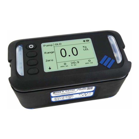
Getting Started Overview The Gasurveyor 700 (GS700) is the fi rst choice for all gas utility applications. Reliable measurements are performed using innovative infrared sensing technology including instantaneous confi rmation that the gas sample is natural gas. This lightweight, rugged instrument is easy to use thanks to an intuitive menu layout on a large display. -
Page 10: Display
Visual Alarm Visual Alarm Soft-Keys Display (includes power key) Display The GS700 is a fully confi gurable instrument, the menu structure and information displayed may vary. Status Bar Gas Readings / Soft Key Options Information Window 1 Gas Readings / Information Window 2 The above display will be used throughout this user guide as the example main display. -
Page 11: Status Bar
The pump is operating at high speed. Gas Ranges The GS700 can detect the following: • Infrared measurement of fl ammable gases (ppm, LEL & volume) - e.g. Methane, Butane • ppm fl ammable gas via sensor or external semiconductor probe •... -
Page 12: Battery Packs
The GS700 has 2 battery options: • Alkaline. • Lithium-Ion rechargeable, fully charge before fi rst use. Only use GMI approved batteries and chargers. Batteries must be charged (or replaced) in a safe area. For further information, see “Battery / Charging”. -
Page 13: Operation
1 second. • The instrument will go through a warm-up sequence. Always switch the instrument on in fresh air. Warm-up Sequence Typical warm-up sequence. GMI logo and instrument type. Progress Bar increases during warm-up (~60s). Instrument: • Type • Serial number •... -
Page 14: Switch Off
GS700 USER GUIDE Sensor zero check. Sensors are zeroed correctly. Typical operating display. Switch Off • Press and hold for 3 seconds. To abort switch off, release B1. -
Page 15: Soundness Test (Optional)
• Unblock the gas inlet (sample path) to continue. • If a leak is detected, in the instrument or probe, the soundness test will fail. • Once the leak has been rectifi ed, press to retry. The GS700 cannot be used until the soundness test has passed. -
Page 16: Modes Of Operation
Modes of Operation The user can confi gure the GS700 to have up to 4 modes of operation, including: • Gas Leak Outdoors (GLO) with or without Barhole testing • Gas Leak Indoors (GLI) • Confi ned Space Monitor (CSM) •... -
Page 17: Gas Leak Outdoors (Glo)
MODES OF OPERATION Gas Leak Outdoors (GLO) In this mode, the GS700 acts as a gas indicator drawing a gas sample, via a probe, where gas is suspected to be present. Alarms are disabled. Typical features: • Pump control • Ability to measure various gas ranges •... -
Page 18: Barhole Testing
Barholes are small holes placed, in the ground, along the route of an underground gas pipe. Gas leak detection is performed by placing a probe into the barhole. The GS700 stores the following measurements when barhole testing: • LEL / Volume Gas readings - peak and sustained •... - Page 19 MODES OF OPERATION The test can be aborted at any time by pressing B1. The result of ‘Barhole number 01’ is displayed on completion. At this point, the instrument must be purged, press B1. To view the results of other barhole tests, press to move through the results.
-
Page 20: Confi Ned Space Monitoring (Csm)
GS700 USER GUIDE Confi ned Space Monitoring (CSM) In this mode the GS700 acts as a safety monitor for use when entering confi ned spaces which may contain hazardous gas mixtures. Typical features: • Automatic datalogging (default - 60 seconds) •... - Page 21 MODES OF OPERATION LTEL readings for toxic gases. Press to return to the Live display. Press to continue. HiHi alarm set-points. Press to return to the Live display. Press to continue. Hi or Lo alarm set-points. Press to return to the Live display. Press to continue.
-
Page 22: Purge
GS700 USER GUIDE Purge In this mode, the GS700 aids in the purging of pipework installations. Alarms are disabled. Typical features: • Pump Control • Measuring ranges - volume gas or oxygen • Sensor Zeroing Search In this mode, the GS700 is used for rapid leak detection. -
Page 23: Pipeline Gas Test
• Red visual top plate LED’s activated Pipeline Gas • Pipeline gas identifi ed The live result will be displayed until the gas reading drops below the decision point (approximately 1.5% GAS). The GS700 can be confi gured to display only the ‘NOT Pipeline Gas!’ results. -
Page 24: Alarms
Alarms When measured gas levels go above or below the instrument alarm set-points, the following alarms may be triggered: • Audible - buzzer will sound (tone will differ depending on alarm type) • Visual - 360 LED bar and top plate LED’s will fl ash red (fl ash will differ depending on alarm type) •... -
Page 25: Gas Alarm Types
ALARMS Gas Alarm Types It is the responsibility of the user to ensure that the alarm set-points are appropriate for the safe operation and legal requirements of the country / industry in which the instrument is being used. By default,gas alarms are set in accordance to international standards. How the instrument responds to the alarm set-points being triggered is confi guration dependent. - Page 26 GS700 USER GUIDE TWA Alarms • A Time Weighted Average (TWA) gas level, is the average gas level measured over a specifi c period of time. » Short Term Exposure Limit (STEL) - 15 minutes » Long Term Exposure Limit (LTEL) - 8 hours •...
-
Page 27: Alarm Mute
ALARMS Geiger Alarm An audible and visual Geiger alarm, enabled in the PPM Flammable range, provides indication of a larger gas concentration via an increasing rate of sounder and LED pulses. Pressing will change the audio / visual (A/V) indicator options: Key Press Geiger Indicators... -
Page 28: Fault Alarm Types
GS700 USER GUIDE Fault Alarm Types Sample Fault A fault with the GS700 fl ow due to the sample path being blocked, water ingress, a blocked fi lter or pump failure. • Functionality is disabled and ‘Sample fault’ fl ashes OFF and ON. - Page 29 ALARMS Calibration Required If confi gured, during instrument warm-up a ‘Cal Due’ message will be displayed. • Press to continue. • Press to switch off. Alternatively, the ‘Cal Due’ message can be confi gured to force the user to switch off the instrument. •...
-
Page 30: Battery / Charging
Battery / Charging The GS700 has 2 battery options: • Alkaline. • Lithium-Ion rechargeable. When the battery level becomes low: • ‘Low Bat’ message will fl ash on the display. Alternates with Battery life is now approximately 30 mins and the batteries require to be replaced or recharged. - Page 31 BATTERY / CHARGING Remove the battery cover. Remove the 3 old batteries. Check battery compartment for damage to spring contacts or corrosion on springs. Insert the 3 new batteries observing correct polarity. Polarity markings indicated in battery compartment. Do not mix old and new alkaline batteries. Do not use rechargeable batteries. Replace battery cover and fasten the base screws.
-
Page 32: Recharging The Battery Pack
GS700 USER GUIDE Recharging the Battery Pack The Lithium-Ion battery pack is recharged using the GMI charger cradle. The battery pack can be charged fi tted to the instrument or separately. Power LED Only use GMI approved batteries and chargers. Batteries must be charged in a safe area. - Page 33 BATTERY / CHARGING The alignment of the GS700, is moulded on the surface of the charger cradle. The charging icon on the instrument will fl ash until fully charged. On completion, remove from charging cradle, as illustrated. Battery Pack Charging Remove the battery pack from the instrument, see “Replacing the Battery...
- Page 34 GS700 USER GUIDE Charging Contacts The orange LED on the battery pack indicates the battery pack is charging. When the LED switches off, the battery pack is fully charged. On completion, remove from charging cradle, as illustrated. Fit the battery pack onto the instrument.
-
Page 35: Replacing The Battery Pack
BATTERY / CHARGING Replacing the Battery Pack The following procedure should be carried out in a safe area. Using the 4mm hex driver (supplied), loosen the 2 instrument base screws. Remove the battery pack. Insert new battery pack. The battery pack can only be fi tted one way. Fasten the base screws. -
Page 36: Maintenance
Outer Casing • The outer, impact resistant, casing of the GS700 may be cleaned using a non-abrasive damp cloth. Rub the cloth over the outer casing to remove any dirt and grime. In extreme cases, a mild soap solution may be used with a non-abrasive cloth to remove stubborn marks. -
Page 37: Replacing The Dust Filter
Clean the inlet nozzle to make sure it’s free from dirt and water. Fit a new dust fi lter into the inlet nozzle. Fit the inlet nozzle. Ensure the inlet nozzle screw thread is correctly located, before fi tting. The GS700 must never be switched on without suitable fi lters installed. -
Page 38: Calibration
GS700 USER GUIDE Calibration The GS700 has been calibrated for a particular fl ammable gas mixture. Where any doubt exists the instrument should be returned to GMI or an authorised distributor for calibration. Different methods of calibration are available: • Automatic Calibration •... -
Page 39: Accessories / Spares
Plastic probe - 80 cm solid end Extended survey probe assembly - 42700 c/w bellows probe Extended survey probe assembly - 42800 c/w swan neck probe Semiconductor fl exi probe assembly (GS700 MUST be fi tted 42200 with a semiconductor probe connection) -
Page 40: Common Spares
Probe Hydrophobic fi lter 10077 Probe Cotton fi lter - Box of 10 42197 Semiconductor fl exi probe assembly fi lter disc For a comprehensive list of accessories, probes, spares and calibration gases, contact your local distributor, or alternatively, GMI Ltd. -
Page 41: Specifi Cation
• Toxic - BS EN 45544 • Oxygen - BS EN 50104 GS700 will indicate if the gas sample is natural gas or Methane, providing: • The measured sample is >1.5% Volume Gas • The sample source contains a minimum of 2% Ethane All the values are typical at normal temperature and pressure. -
Page 42: Instrument Specifi Cation
Power Source Only use approved alkaline batteries. Alkaline: DURACELL: PROCELL (MN1300) or INDUSTRIAL (ID1300) ANSMANN: INDUSTRIAL or X-POWER Approved Batteries PANASONIC: EVOLTA Rechargeable: GMI rechargeable battery pack Alkaline: 15 hours Battery Life Rechargeable: 20 hours Warranty 2 years (excluding consumables) -
Page 43: Alarm Set-Points
SPECIFICATION *500 session logs, each log can include: • Date / time • User ID • Modes of operation Datalogging • Gas readings / activated alarms • Calibration data • Barhole logs / GPS location data Oldest log will be overwritten when full. * Session log: the time from instrument switch on, until instrument switch off. -
Page 44: Soft-Key Button Glossary
GS700 USER GUIDE Soft-Key Button Glossary The following table shows Soft-Key options that may be displayed. Feature Description Abort Abort testing Acknowledge alarm Audio / visual Barhole test Clear Clear present readings Show GPS coordinates Live Return to live gas readings... -
Page 45: Field Calibration (Optional)
Appendix A Field Calibration (Optional) This feature allows simple calibration to be used in the fi eld, without the use of the automatic and manual calibration set-ups previously highlighted in this User Guide. The following kit is required to perform fi eld calibration: •... - Page 46 FIELD CALIBRATION Connect the tubing from the regulator to the instrument inlet nozzle. Wait for the instrument gas to settle. If the displayed reading does not correspond to the concentration of calibration gas, by pressing the appropriate soft-key, the displayed gas value can be altered until the gas value corresponds to the concentration of calibration gas.
-
Page 47: Warranty
Gas / Non pipeline Gas test function is for indication and advisory purposes only and should not be relied upon as the sole indicator for confi rming the type of gas present in the environment. GMI shall not therefore be held liable for any direct costs or consequential costs, losses or expenses incurred by the user whilst solely relying on a Pipeline Gas test function in order to determine the presence of Piped natural gas. -
Page 48: Contact Details
Head Offi ce Inchinnan Business Park Renfrew Scotland PA4 9RG Tel: +44 (0)141 812 3211 Fax: +44 (0)141 812 7820 sales@gmiuk.com www.gmiuk.com Service & Calibration Centre 25 Cochran Close Crownhill Milton Keynes MK8 0AJ Tel: +44 (0)1908 568 867 Fax: +44 (0)1908 261 056 service@gmiuk.com Gas Measurement Instruments Ltd...
Need help?
Do you have a question about the GS700 and is the answer not in the manual?
Questions and answers