Table of Contents
Advertisement
Advertisement
Table of Contents

Related Manuals for GMI Gasurveyor 700


Summary of Contents for GMI Gasurveyor 700
- Page 1 Gasurveyor 700 Gas Measurement Instruments Ltd...
-
Page 2: Notification Icons
© 2016 Gas Measurement Instruments Ltd. This user guide is copyright of Gas Measurement Instruments Ltd (GMI) and the information contained within is for use only with Gasurveyor 700 instruments. Reproduction, in whole or part, without written permission of GMI is prohibited. -
Page 3: Essential Health & Safety Requirements
• The equipment must not be subject to prolonged exposure to light when not in use. Any right of claim relating to product liability or consequential damage to any third party against GMI is removed if the warnings are not observed. -
Page 4: Equipment Parameters
: 6.78V Temperature Range: -20 C ≤ Ta ≤ 44 Certification Gasurveyor 700 instruments are certified as: II 2 G Ex db ia IIC T4 Gb -20 C ≤ Ta ≤ 50 ATEX * II 2 G Ex db ia IIB T3 Gb -20 C ≤... -
Page 5: Additional Safety Details - Csa Only
Additional Safety Details - CSA Only Before each days Usage, test on a known concentration of methane, equivalent to CAUTION: 25 - 50% of full scale concentration. Accuracy must be within 0 to +20% of actual. Accuracy may be corrected by calibration. (Refer to Chapter: ‘CALIBRATION’). Avant chaque utilisation journalière, testez la réaction de l’appareil en utilisant ATTENTION: une concentration connue en méthane, correspondant à... -
Page 6: Table Of Contents
Contents Notification Icons .................. 2 Copyright ....................2 Essential Health & Safety Requirements ........... 3 General ..........................3 Battery / Charging ......................3 Areas Of Use ........................3 Storage, Handling And Transit ....................3 Special Conditions Of Use ....................3 Equipment Parameters ......................4 Certification ................... 4 Additional Safety Details - CSA Only .................5 Getting Started .................. - Page 7 Modes of Operation ................16 Gas Leak Outdoors (GLO) ....................17 Additional Functions ......................17 Pipeline Gas Test (PGT) ....................18 Purge ..........................19 Search ..........................19 Barhole Testing ........................20 Confined Space Monitoring (CSM) ..................22 Alarms ....................24 Alarm Acknowledge ......................24 Gas Alarm Types ......................25 Alarm Mute ........................27 Confidence Signal ......................27...
- Page 8 Accessories / Spares ................42 Accessories ........................42 Common Spares ......................43 Specification ..................44 Instrument Performance ....................44 Instrument Specification ....................45 Alarm Set-points ......................46 Soft-Key Button Glossary ....................47 Warranty ..................... 48 Liability ....................48 Customer Support ................48 Disposal ....................48 Contact Details ..................49...
-
Page 9: Getting Started
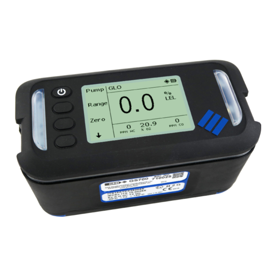
Getting Started Overview The Gasurveyor 700 (GS700) is the first choice for all gas utility applications. Reliable measurements are performed using innovative infrared sensing technology including instantaneous confirmation that the gas sample is natural gas. This lightweight, rugged instrument is easy to use thanks to an intuitive menu layout on a large display. -
Page 10: Display
GS700 USER GUIDE Visual Alarm Visual Alarm Soft-Keys Display (includes power key) Display The GS700 is a fully configurable instrument, the menu structure and information displayed may vary. Status Bar Gas Readings / Soft Key Options Information Window 1 Gas Readings / Information Window 2 The above display will be used throughout this user guide as the example main display. -
Page 11: Status Bar
GETTING STARTED Status Bar Displays current operating mode. Icons provide information about instrument status. Status Bar Status bar icons: Icon Description Battery Indicates the current battery level. Datalogging Indicates a manual or automatic datalog is being undertaken. Geiger - audible & visual alarms off Indicates the audible and visual alarms are switched off when using the Geiger feature. -
Page 12: Battery Packs
Battery Packs The GS700 has 2 battery options: • Alkaline. • Lithium-Ion rechargeable, fully charge before first use. Only use GMI approved batteries and chargers. Batteries must be charged (or replaced) in a safe area. For further information, see “Battery / Charging”. -
Page 13: Operation
1 second. • The instrument will go through a warm-up sequence. Always switch the instrument on in fresh air. Warm-up Sequence Typical warm-up sequence. GMI logo and instrument type. Progress Bar increases during warm-up (~60s). Instrument: • Type • Serial number •... -
Page 14: Switch Off
GS700 USER GUIDE Sensors are zeroed correctly. Typical operating display. Switch Off • Press and hold for 3 seconds. To abort switch off, release B1. The next time the GS700 is switched on, the display will show the operating mode used prior to switch off. -
Page 15: Soundness Test (Optional)
OPERATION Soundness Test (Optional) A soundness test verifies the instrument and probe are not leaking. • A soundness test is performed during instrument warm-up. • Block the gas inlet (sample path). • The test will last for 5 seconds. • If the instrument and probe are not leaking the soundness test will pass. -
Page 16: Modes Of Operation
Modes of Operation The user can configure the GS700 to have up to 4 modes of operation, including: • Gas Leak Outdoors (GLO) • Pipeline Gas Test (PGT) • Purge • Search • Confined Space Monitor (CSM) • Pressing will display the configured modes of operation. -
Page 17: Gas Leak Outdoors (Glo)
GS700 USER GUIDE Gas Leak Outdoors (GLO) In this mode, the GS700 acts as a gas indicator drawing a gas sample, via a probe, where gas is suspected to be present. Alarms are disabled. Typical features: • Pump control • Ability to measure various gas ranges •... -
Page 18: Pipeline Gas Test
MODES OF OPERATION Pipeline Gas Test (PGT) In this mode, the GS700 is used to discriminate between pipeline gas (natural gas) and non pipeline gas (e.g. landfill or swamp gas). Typical features: • Discrimination between gases • Pump Control • Sensor Zeroing When sample testing, the GS700 discriminates the gas and displays the results, as follows: Pipeline Gas... -
Page 19: Purge
GS700 USER GUIDE PGT can be configured to be an additional feature running in the background. In this configuration, from any mode, detection of Non Pipeline Gas will be displayed. Purge In this mode, the GS700 aids in the purging of pipework installations. -
Page 20: Barhole Testing
MODES OF OPERATION Barhole Testing Barhole testing is normally contained within a mode, e.g. GLO mode. Barholes are small holes placed, in the ground, along the route of an underground gas pipe. Gas leak detection is performed by placing a probe into the barhole. The GS700 stores the following measurements when barhole testing: •... - Page 21 GS700 USER GUIDE The test can be aborted at any time by pressing B1. The result of ‘Barhole number 01’ is displayed on completion. At this point, the instrument must be purged, press B1. To view the results of other barhole tests, press to move through the results.
-
Page 22: Confined Space Monitoring (Csm)
MODES OF OPERATION Confined Space Monitoring (CSM) In this mode the GS700 acts as a safety monitor for use when entering confined spaces which may contain hazardous gas mixtures. Typical features: • Automatic datalogging (default - 60 seconds) • View maximum / minimum / STEL / LTEL gas readings •... - Page 23 GS700 USER GUIDE LTEL readings for toxic gases. Press to continue. Press to return to the Live display. HiHi alarm set-points. Press to continue. Press to return to the Live display. Hi or Lo alarm set-points. Press to continue. Press to return to the Live display.
-
Page 24: Alarms
GS700 USER GUIDE Alarms When measured gas levels go above or below the instrument alarm set-points, the following alarms may be triggered: • Audible - buzzer will sound (tone will differ depending on alarm type) • Visual - 360 LED bar and top plate LED’s will flash red (flash will differ depending on alarm type) •... -
Page 25: Gas Alarm Types
ALARMS Gas Alarm Types It is the responsibility of the user to ensure that the alarm set-points are appropriate for the safe operation and legal requirements of the country / industry in which the instrument is being used. By default,gas alarms are set in accordance to international standards. How the instrument responds to the alarm set-points being triggered is configuration dependant. - Page 26 GS700 USER GUIDE TWA Alarms • A Time Weighted Average (TWA) gas level, is the average gas level measured over a specific period of time. » Short Term Exposure Limit (STEL) - 15 minutes » Long Term Exposure Limit (LTEL) - 8 hours •...
-
Page 27: Alarm Mute
ALARMS Geiger Alarm An audible and visual Geiger alarm, enabled in the PPM Flammable range, provides indication of a larger gas concentration via an increasing rate of sounder and LED pulses. Pressing will change the audio / visual (A/V) indicator options: Key Press Geiger Indicators... -
Page 28: Fault Alarm Types
GS700 USER GUIDE Fault Alarm Types Sample Fault A fault with the GS700 flow due to the sample path being blocked, water ingress, a blocked filter or pump failure. • Functionality is disabled and ‘Sample fault’ flashes OFF and ON. •... - Page 29 ALARMS Calibration Required If configured, during instrument warm-up a ‘Cal Due’ message will be displayed. • Press to continue. • Press to switch off. Alternatively, the ‘Cal Due’ message can be configured to force the user to switch off the instrument. •...
-
Page 30: Battery / Charging
GS700 USER GUIDE Battery / Charging The GS700 has 2 battery options: • Alkaline. • Lithium-Ion rechargeable. When the battery level becomes low: • ‘Low Bat’ message will flash on the display. Alternates with Battery life is now approximately 30 mins and the batteries require to be replaced or recharged. - Page 31 BATTERY / CHARGING Remove the battery cover. Remove the 3 old batteries. Check battery compartment for damage to spring contacts or corrosion on springs. Insert the 3 new batteries observing correct polarity. Polarity markings indicated in battery compartment. Do not mix old and new alkaline batteries. Do not use rechargeable batteries. Replace battery cover and fasten the base screws.
-
Page 32: Recharging The Battery Pack
GS700 USER GUIDE Recharging the Battery Pack The Lithium-Ion battery pack is recharged using the GMI charger cradle. The battery pack can be charged fitted to the instrument or separately. Power LED Only use GMI approved batteries and chargers. Batteries must be charged in a safe area. - Page 33 BATTERY / CHARGING The alignment of the GS700, is moulded on the surface of the charger cradle. The charging icon on the instrument will flash until fully charged. On completion, remove from charging cradle, as illustrated. Battery Pack Charging Remove the battery pack from the instrument, see replacing the battery pack.
- Page 34 GS700 USER GUIDE Charging Contacts The orange LED on the battery pack indicates the battery pack is charging. When the LED switches off, the battery pack is fully charged. On completion, remove from charging cradle, as illustrated. Fit the battery pack onto the instrument.
-
Page 35: Replacing The Battery Pack
BATTERY / CHARGING Replacing the Battery Pack The following procedure should be carried out in a safe area. Using the 4mm hex driver (supplied), loosen the 2 instrument base screws. Remove the battery pack. Insert new battery pack. The battery pack can only be fitted one way. Fasten the base screws. -
Page 36: Maintenance
GS700 USER GUIDE Maintenance Cleaning Display Window • An optical cloth MUST be used to clean the display window, as the window is susceptible to scratches. In extreme cases a mild screen solution may be used with the optical cloth to remove stubborn stains. -
Page 37: Replacing The Dust Filter
MAINTENANCE Replacing the Dust Filter Cotton particulate (dust) filters, minimise the danger of dust ingress. Removing the inlet nozzle allows access to the dust filter. Using a small coin or appropriate sized flat bladed screwdriver, remove the inlet nozzle. Remove the dust filter from the inlet nozzle. Dust Filter Inlet Nozzle The dust filter should be removed for inspection periodically. -
Page 38: Bump Test (Optional)
• PC / flexiCal Plus software • Standalone Mode Automatic bump test equipment, consisting of both hardware and software, are manufactured by GMI. For further details contact GMI or an authorised distributor. Manual Bump Test Requires the user to control the delivery of gas during testing. - Page 39 BUMP TEST After instrument warm-up the bump test menu will be displayed. Gas should now be applied to the instrument. The bump test can be aborted at any time by pressing B4. Connect the ‘On Demand Flow Regulator’ to the gas cylinder.
- Page 40 GS700 USER GUIDE Bump Fail A manual bump test will fail if: • A measured gas reading is above / below the configured limit. • The audible and visual alarms fail to alert the user. Press to confirm a fail. The instrument must be switched off, press for 3 seconds.
-
Page 41: Calibration
Calibration The GS700 has been calibrated for a particular flammable gas mixture. Where any doubt exists the instrument should be returned to GMI or an authorised distributor for calibration. Different methods of calibration are available: • Automatic Calibration • Manual Calibration... -
Page 42: Accessories / Spares
GS700 USER GUIDE Accessories / Spares Accessories GMI Part No. Part Description 49460 Charger cradle c/w universal power supply Auto calibration package c/w GDUnet, s/w & 6 mm fittings 14750X(Q) (Q - for 1/4 in. fittings) 99118 On demand regulator valve... -
Page 43: Common Spares
Instrument Dust filter - Box of 30 12358 Probe Hydrophobic filter 10077 Probe Cotton filter - Box of 10 42197 Semiconductor flexi probe assembly filter disc For a comprehensive list of accessories, probes, spares and calibration gases, contact your local distributor, or alternatively, GMI Ltd. -
Page 44: Specification
GS700 USER GUIDE Specification Instrument Performance Sensor Type Range Resolution 0 - 1000 ppm 1 ppm Semiconductor 0 - 10,000 ppm 1 ppm 0 - 9.9% 0.1% Infrared 10 - 100% 0 - 5% 0.1% Volume Gas Infrared 5% - 100% Electrochemical 0 - 1000 ppm 1 ppm... -
Page 45: Instrument Specification
Alkaline Batteries: 3 x size ‘D’ (LR20), or Power Source Rechargeable Battery Pack Alkaline: Duracell - MN1300 or ID1300 Ansmann - Industrial or XPower Approved Batteries Panasonic - EVOLTA Rechargeable: GMI rechargeable battery pack Battery Life 20 hours (Alkaline & Rechargeable) Warranty 2 years (excluding consumables) -
Page 46: Alarm Set-Points
GS700 USER GUIDE *500 session logs, each log can include: • Date / time • User ID • Modes of operation Datalogging • Gas readings / activated alarms • Calibration / bump test data • Barhole logs / GPS location data Oldest log will be overwritten when full. -
Page 47: Soft-Key Button Glossary
SPECIFICATION Soft-Key Button Glossary The following table shows Soft-Key options that may be displayed. Feature Description Abort Abort testing Acknowledge alarm Audio / visual Barhole test Clear Clear present readings Shows additional functions Func Show GPS coordinates Return to live gas readings Live Manual datalog Available operating modes... -
Page 48: Warranty
Thank you for reading this data sheet. For pricing or for further information, please contact us at our UK Office, using the details below. UK Office Keison Products, P.O. Box 2124, Chelmsford, Essex, CM1 3UP, England. Tel: +44 (0)330 088 0560 Fax: +44 (0)1245 808399 Email: sales@keison.co.uk...
Need help?
Do you have a question about the Gasurveyor 700 and is the answer not in the manual?
Questions and answers