
Related Manuals for GMI Gasurveyor 500


Summary of Contents for GMI Gasurveyor 500
- Page 1 Gasurveyor 500 User Handbook Distributed By: 713-844-1300 info@heathus.com www.heathus.com...
- Page 2 GASURVEYOR 500 USER HANDBOOK Issue /0 /1 Part Number: 42153 GMI welcomes comments on all our publications. Your comments can be of great value in helping us to improve our customer publications. Please send any comments that you have to our Sales Department at GMI.
-
Page 3: Copyright
Instruments Ltd is prohibited. Reverse engineering is not permitted. LIABILITY Every care has been taken in the preparation of this document, but GMI Ltd do not accept any responsibility for errors or omissions and their consequences. Information in this document is subject to change without notice. This document does not constitute a specification or basis for a contract. -
Page 4: Safety
The combustion chamber is a flameproof assembly and must not be opened in the presence of a flammable atmosphere. • Gasurveyor 500 series instruments are certified as EEx iad IIC T4 (-20 o C < Tamb < 50 o C). BAS01ATEX2292 II 2 G. -
Page 5: Declaration Of Conformity
DECLARATION OF CONFORMITY Refer to current Declaration of Conformity document Part No. 42907 (supplied with product) - Page 6 GASURVEYOR 500 USER HANDBOOK...
-
Page 7: Revision Record
REVISION RECORD Date Issue Description Of Change 18/08/00 New Handbook 09/05/01 Revised to reflect generic instrument options and features 06/01/03 Revised to include Geiger clarification and effect of CN 2313 17/07/03 Revised to include effect of CN 2291 26/07/04 Revised to include Appendix C (translations) 08/06/07 Revised to include Marine... - Page 8 GASURVEYOR 500 USER HANDBOOK...
-
Page 9: Table Of Contents
CONTENTS COPYRIGHT ..............i LIABILITY ............... i MODIFICATION NOTICES ..........i SOFTWARE ..............i DISPOSAL ADVICE ............i SAFETY ................. ii AREAS OF USE ............. ii STORAGE, HANDLING AND TRANSIT ......ii DECLARATION OF CONFORMITY ....iii REVISION RECORD ........v INTRODUCTION .......... - Page 10 GASURVEYOR 500 USER HANDBOOK Oxygen, 0 – 25% ............ 2-4 Toxic Ranges ............2-5 Alarms ................ 2-5 Alarm Functions ............2-6 Geiger Indication ............. 2-7 Datalogging ..............2-7 CSM Mode ............... 2-8 CGI Mode ..............2-8 Construction .............. 2-8 Batteries ..............2-9 Disposable Alkaline (LR20) Dry Cell Batteries ..
- Page 11 CONTENTS Clearing Alarms ............3-6 Notes on (default) CSM mode: ........ 3-7 Summary of (default) CSM Button Operation ..3-7 Combustible Gas Indicator (CGI) Operation ....3-8 Switching On in CGI Mode ........3-8 Calibration Date Features ........3-9 Switching Off the Instrument Pump ......3-9 Switching Off ............
- Page 12 GASURVEYOR 500 USER HANDBOOK CALIBRATION ..........5-1 Calibration Validity ............5-2 ACCESSORIES .......... 6-1 ADDITIONAL INFORMATION ....... 7-1 Training ..............7-1 World Wide Web ............7-1 TYPICAL OPERATING PARAMETERS ..A-1 Size ................ A-2 Weight ..............A-2 Operating Temperature .......... A-2 Humidity ..............
- Page 13 CONTENTS Zeroing the Instrument ..........B-4 Field Calibration Procedure ........B-5 Edit Cal Due Date ............B-8 Quit And Save Changes ........B-9 Quit Without Saving Changes ........ B-9 QUICK OPERATING INSTRUCTIONS ..C-1 English ............... C-2 L'italiano (Italian) ............C-6 Español (Spanish) ...........
- Page 14 GASURVEYOR 500 USER HANDBOOK...
-
Page 15: Introduction
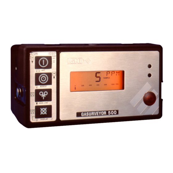
The instrument is designed to the latest standards and is certified for use in Hazardous Areas. Figure 1-1 Gasurveyor 500 series Instrument The Gasurveyor 500 can contain up to six gas ranges with the following ranges being possible: •... - Page 16 Gasurveyor 500. The instrument that this manual has been supplied with is part of the Gasurveyor 500 series, e.g. Gasurveyor 521: LEL/Vol ; Oxygen. Gasurveyor 531: LEL/Vol ; Oxygen ; Hydrogen Sulphide.
- Page 17 Audible and Visual Geiger indication, enabled in the PPM Flammable range, provides indication of gas concentration increase via the increased rate of sounder and LED pulse. • Manual and automatic datalogging. • Directly interfaces with the GMI Auto Test Calibration Systems.
- Page 18 GASURVEYOR 500 USER HANDBOOK...
-
Page 19: General Information
GENERAL INFORMATION GENERAL INFORMATION Ranges of Operation LEL, 0 to 100% The LEL range indicates the explosibility of the flammable gas in the sample. This is displayed as a percentage of the lower explosive limit (LEL) of the gas. The instrument range is displayed in the top right corner of the display as % LEL. -
Page 20: Volume Gas, 0 To 100
GASURVEYOR 500 USER HANDBOOK Volume Gas, 0 to 100 % This range displays the total volume of a specific flammable gas with respect to air. The calibration gas is shown on the service label and for the purpose of this handbook is assumed to be methane. - Page 21 GENERAL INFORMATION correction techniques are used to minimise drift. The ppm range includes a manual zeroing procedure. The ppm range has the option of using a ‘threshold’. By this, we mean that we can display either a blank screen or simply a zero (0) on the display, up to a pre-set level. This allows small readings, which may not be due to the gas we wish to find or very small amounts of gas, to be ignored if they fall below any pre-set action levels.
-
Page 22: Threshold Display Options
GASURVEYOR 500 USER HANDBOOK When the instrument is switched on, the visual Geiger indication is operational. To activate the audible Geiger indication, press and hold Switch Four ( Threshold Display Options The ppm range will by default, if a threshold is selected, display below the threshold as zero (0) on the screen. -
Page 23: Toxic Ranges
The instrument, by default, will have alarm levels for the Flammable LEL, Oxygen, and Toxic gases pre-set. The Gasurveyor 500 series has the facility to have two (2) instantaneous alarm levels for each range in the instrument. These are described as LOW and HIGH. By default, only the high instantaneous is activated. -
Page 24: Alarm Functions
GASURVEYOR 500 USER HANDBOOK When operating in Confined Space Monitor (CSM) mode, the instrument has two (2) toxic monitoring alarm levels set by default. These are the STEL (Short Term TWA) and LTEL (Long Term TWA). The option is to have these two alarm levels disabled. -
Page 25: Geiger Indication
(if activated) and the LED, pulse at an increasing rate. Datalogging The Gasurveyor 500 series memory can store up to 1000 logged entries which are dependent on number of Gas ranges and duration of each ON / OFF session. The memory will overwrite entries in the event of an overflow. -
Page 26: Csm Mode
GASURVEYOR 500 USER HANDBOOK CSM Mode The Gasurveyor 500 instruments, by default, have automatic and manual datalogging enabled when operating in CSM mode. During automatic datalogging the instrument stores the values of all gas ranges together with the current time and date at 60 second intervals. -
Page 27: Batteries
The instrument will then turn off. There are three GMI Battery Chargers: a Standard Charger, a Flatbed Charger and a Smart Charger. The Smart Charger has both slow and fast charge options as well as a serial link for communications with the instrument. -
Page 28: Filters
GASURVEYOR 500 USER HANDBOOK Filters A number of different filter types are available from GMI. The minimum recommendation is a cotton particulate filter and a hydrophobic filter which are incorporated in the probe handle assembly, available as an accessory. Filters must be checked at frequent intervals and where appropriate changed to ensure a clean sample path. -
Page 29: Operating Instructions
OPERATION OPERATING INSTRUCTIONS Operating Modes The Gasurveyor 500 is a dual configuration instrument. It operates as a Confined Space Monitor (CSM) or as a Combustible Gas Indicator (CGI) depending on the button used to switch it on. For Confined Space Monitor operation the instrument must be switched on by pressing and holding Switch One ( for approximately one second. -
Page 30: Confined Space Monitor (Csm) Operation
GASURVEYOR 500 USER HANDBOOK Confined Space Monitor (CSM) Operation In this mode the instrument operates as a safety monitor for use when entering confined spaces which may contain hazardous gas mixtures (flammable, toxic and/or asphyxiant). The instrument samples the ambient... - Page 31 OPERATION Note: * Battery status is displayed as either OK or LO at start-up. Figure 3-2 CSM Warm Up...
-
Page 32: Calibration Date Features
GASURVEYOR 500 USER HANDBOOK Calibration Date Features At the end of warm-up and before the Gasurveyor 500 instrument is ready for measuring, the instrument will indicate on the display when the next calibration is due. This will be displayed as month and year, as in Figure... -
Page 33: Datalogging (Default)
When automatic datalogging is on, the STORE flag is permanently displayed. Cycling Through the Display Options The Gasurveyor 500 instruments can be enabled to allow the user to view the minimum and maximum readings for each range during the instrument’s operation since switch... -
Page 34: Clearing Alarms
GASURVEYOR 500 USER HANDBOOK Table 3-4 Display Options Clearing Alarms A double press of Switch Four ( ) will clear an alarm if latching, or acknowledge the alarm for 60 seconds if non-latching. Double pressing will only cancel the alarm when the gas level is below the threshold set in the instrument. -
Page 35: Notes On (Default) Csm Mode
OPERATION Notes on (default) CSM mode: • Alarms are always active in CSM mode. • The pump cannot be switched off in CSM mode. • In CSM mode the instrument does not switch off automatically. • In CSM mode automatic datalogging is enabled by default. -
Page 36: Combustible Gas Indicator (Cgi) Operation
GASURVEYOR 500 USER HANDBOOK Combustible Gas Indicator (CGI) Operation In this mode the instrument operates as a gas indicator drawing a sample via a probe from points where gas is suspected to be present. Alarms, by default, are disabled in CGI mode, as the instrument is generally used for measuring gas levels rather than monitoring for the presence of gas. -
Page 37: Calibration Date Features
OPERATION Calibration Date Features At the end of warm-up and before the Gasurveyor 500 instrument is ready for measuring, the instrument will indicate on the display when the next calibration is due. This will be displayed as month and year, as shown in... -
Page 38: Changing Range
GASURVEYOR 500 USER HANDBOOK Changing Range Each single press of Switch Two ( ) changes the gas range selected. The display cycles through the available ranges in the order PPM/LEL/GAS – O – Toxic 1 – Toxic 2 – PPM/LEL/GAS etc. -
Page 39: Manual Datalogging (Default)
OPERATION Manual Datalogging (Default) A single press of Switch Three ( ) performs a manual datalog. This is confirmed by the STORE flag being displayed for 1 second and the buzzer sounding. Notes on CGI mode (Default): • Alarms do not operate in CGI mode. •... -
Page 40: Operator Messages / Fault Flags
GASURVEYOR 500 USER HANDBOOK Operator Messages / Fault Flags Various messages can appear on the LCD screen to indicate instrument status. ‘SAMPLE’ This indicates that the pump is running and the instrument is sampling. ‘OFF’ This indicates that the instrument is about to switch off. - Page 41 OPERATION ‘ZERO FAULT’ This indicates that the zero is outwith its calibration limits. Switch the instrument off and then on again in fresh air. If the fault does not clear, leave the instrument on for a period of 30 minutes then switch off and on again. If the fault still does not clear, return the instrument for servicing.
- Page 42 GASURVEYOR 500 USER HANDBOOK The message is also displayed if the measurement falls below -99 (incorrect zero setting) in either ppm or the toxic ranges. ‘1’ This message which can also appear after power on, indicates that a calibration data error has been detected.
-
Page 43: Operator Maintenance
OPERATOR MAINTENANCE OPERATOR MAINTENANCE Rechargeable Battery Pack Three battery chargers are available from GMI, a Standard Charger, a Flatbed Charger and a Smart Charger. Standard Charger The GMI Standard Charger takes approximately 14 hours to charge a flat battery. -
Page 44: Flatbed Charger
Select Switch can then be set to STAND-BY, where a trickle charge will maintain the battery in a fully charged state of readiness. Smart Charger The GMI Smart Charger provides both fast and standard charging facilities and can charge an instrument and spare... -
Page 45: Replacing The Battery Pack
OPERATOR MAINTENANCE battery pack simultaneously. Using the standard charging option, a battery pack can be recharged in 12 hours from a fully discharged state. Using the fast charge option a battery pack can be 90% recharged in approximately 60 minutes and fully recharged in 120 minutes. To ensure optimum life length, the rechargeable pack should be fully discharged and charged on a regular basis of, at least, every three months. -
Page 46: Recharging The Battery Pack
Replacing Alkaline (LR20) Dry Cell Batteries All four batteries should be replaced at any one time and in a safe area. GMI only recommend the use of Energiser or Duracell batteries. 1) Loosen the two instrument base screws (4mm hex) using the special tool provided. -
Page 47: Filter Replacement
OPERATOR MAINTENANCE 2) Remove battery cover. 3) Remove the old batteries. 4) Check battery compartment for damage to spring contacts or corrosion on springs. Caution: Under no circumstances should rechargeable batteries be fitted in place of Alkaline batteries. 5) Insert four new batteries observing correct polarity indication in battery compartment base. - Page 48 GASURVEYOR 500 USER HANDBOOK To replace the filter(s) shown below, proceed as follows: 1) Unscrew the probe handle assembly. Cotton Particulate Filter Hydrophobic Filter Probe Handle Assembly 2) Remove the cotton particulate filter and discard. 3) Remove the hydrophobic filter.
-
Page 49: Calibration
CALIBRATION The instrument has been calibrated for a particular flammable gas mixture. Where any doubt exists the instrument should be returned to GMI or an authorised distributor for calibration. Four methods of calibration are possible: • Field Calibration. See APPENDIX B, FIELD CALIBRATION for further details. -
Page 50: Calibration Validity
12 month period can be expected. This is no guarantee, however, as the precise application of the product is unknown to GMI. Individual codes of practice may dictate shorter periods. Regular checking establishes a pattern of reliability and enables the calibration check period to be modified in line with operational experience. -
Page 51: Accessories
ACCESSORIES ACCESSORIES Accessories Gasurveyor Series Instrument Part Number Description 13844 Standard Charger c/w Universal Power Supply 13179 Standard Charger excl. Power Supply 12988 12v Car Charger Lead - Standard Charger Only 13163 5-Way Lead for Multi-Charging - Standard Charger Only 42744 Flatbed Charger c/w Universal Power Supply... - Page 52 GASURVEYOR 500 USER HANDBOOK 12393 Plastic Probe - Solid End 80cm. (2ft.6ins.) approx. 12394 Flexible Probe - Open End (Leak Tracing) 35cm. (1ft.2ins.) approx. 12480 Plastic Probe - Solid End (General Leak Detection) 35cm. (1ft.2ins.) approx. 13427 Plastic Probe - Open End (General Leak Detection) 35cm.
- Page 53 35m (113ft.9ins.) Conductive Sample Line c/w Sampling Connector & Filters 12370/2 Shoulder Harness 12371 30mm Waist Belt 12451 4mm Hex. Driver (for Base Screws) 42153 User Handbook Note: For other sampling probes and accessories, and for calibration gases, contact GMI Ltd.
- Page 54 GASURVEYOR 500 USER HANDBOOK...
-
Page 55: Additional Information
ADDITIONAL INFORMATION Training Training courses are available on all our products. Contact our Marketing Department for further details: Tel: +44 (0) 141 812 3211 Fax: +44 (0) 141 812 7820 e-mail: sales@gmiuk.com World Wide Web Visit our web site at www.gmiuk.com... - Page 56 GASURVEYOR 500 USER HANDBOOK...
-
Page 57: Typical Operating Parameters
TYPICAL OPERATING PARAMETERS TYPICAL OPERATING PARAMETERS Typical operating parameters are as follows: Range Resolution Zero Accuracy Range Stability 0 to 1000 ppm 5 ppm +/- 30 ppm 5% +/- 25 ppm 0 to 10% 0.1% +/- 0.5% 10 to 100% 2% +/- 1% LEL Volume 0 to 100%... -
Page 58: Size
GASURVEYOR 500 USER HANDBOOK Size 180mm (7.08”) x 95mm (3.74”) x 105mm (4.13”) Weight 1.7kg (3.75lbs.) with alkaline batteries Operating Temperature C to 50 C (-4 F to 122 Humidity 0 – 95% RH Construction Moulded polypropylene case protected to IP54... -
Page 59: Power Source
TYPICAL OPERATING PARAMETERS Power Source 4 ‘D’ size alkaline cells providing approximately 15 hours runtime at 20 C (68 F).. Rechargeble (NiCd) battery pack providing approximately 9 hours runtime at 20 C (68... - Page 60 GASURVEYOR 500 USER HANDBOOK...
-
Page 61: Field Calibration
Field calibration allows simple calibration to be carried out in the field without the use of additional test equipment. Other calibration procedures require the use of the GMI Manual Calibration software or the Workshop System. There are fundementals, in terms of instrument calibration, that should be noted: •... - Page 62 GASURVEYOR 500 USER HANDBOOK Figure B-1 Switch Functions To simplify switch operation when calibrating the instrument, an overlay card, shown in Figure B-2, is available and can be placed over the top face of the instrument to identify calibration switch functions.
-
Page 63: Selectable Ranges In Fcm
FIELD CALIBRATION Selectable Ranges in FCM When in FCM the following ranges are manually selectable by pressing Switch Two ( ) : PPM, LEL, Volume GAS, Oxygen, Toxic Range 1, Toxic Range 2. Cal Due Date can also be edited in FCM. Entering FCM 1) Switch the instrument on and allow it to complete its warm-up checks. -
Page 64: Zeroing The Instrument
GASURVEYOR 500 USER HANDBOOK In CAL mode, the instrument switches have the functions shown in Figure B-4. – – Figure B-4 FCM Switch Functions Zeroing the Instrument 1) Enter FCM. See the previous section ENTERING FCM. 2) Double press Switch Two ( ) to zero the current gas range. -
Page 65: Field Calibration Procedure
FIELD CALIBRATION 4) Repeat steps 2 and 3 until all gas ranges have been zeroed. 5) Proceed to FIELD CALIBRATION PROCEDURE to calibrate the instrument. Field Calibration Procedure 1) Zero gas ranges before attempting calibration. See previous section ZEROING THE INSTRUMENT for details. - Page 66 GASURVEYOR 500 USER HANDBOOK 4) Turn the regulator valve counter clockwise to open the valve slightly. Make sure that the gas is flowing before connecting the sample tubing to the instrument, otherwise an instrument sample fault may occur. 5) Connect tubing from regulator to instrument inlet...
- Page 67 FIELD CALIBRATION 8a) A single press of Switch Three ( ) will produce small incremental changes to increase display reading, or a single press of Switch Four ( will produce small decremental changes to decrease display reading, until the displayed gas value corresponds to the concentration of the calibration gas.
-
Page 68: Edit Cal Due Date
GASURVEYOR 500 USER HANDBOOK 11) Make sure that the regulator valve is in the fully closed position (Off) then disconnect the regulator from the gas cylinder (turn regulator body in a counter clockwise direction). 12) Replace the cap on the calibration gas cylinder. -
Page 69: Quit And Save Changes
3) Each single press of Switch Three ( ) will increase date, and each single press of Switch Four ( ) will decrease date, until the required Cal Due Date is displayed. 4) When required Cal Due Date is displayed, press and hold Switch Four ( ) to exit SPAN mode. - Page 70 GASURVEYOR 500 USER HANDBOOK B-10...
-
Page 71: Quick Operating Instructions
QUICK OPERATING INSTRUCTIONS The following multi-language instructions provide the user with a quick operation guide for the . . Gasurveyor 500 series instrument. Each language and pages reference is as follows: • English - pages C-2 to C-5 • L'italiano (Italian) - pages C-6 to C-9 •... - Page 72 1.2.7 of Annex II of the ATEX Directive 94/9/ Any right of claim relating to product liability or consequential damage to any third party against GMI is removed if the warnings are not observed. AREAS OF USE Exposure to certain chemicals can result in a loss of sensitivity of the flammable sensor.
- Page 73 Gasurveyor 500 - Operating Instructions OPERATOR MESSAGES / FAULT FLAGS Various messages can appear on the LCD screen to indicate instrument status. ‘SAMPLE’ Indication that the pump is running and the instrument is sampling. ’OFF’ Indication that the instrument is about to switch off. This command can be cancelled by a single press of any button.
- Page 74 GAS MEASUREMENT INSTRUMENTS LTD. OPERATION SWITCH 1 SWITCH 2 SWITCH 3 SWITCH 4 GASURVEYOR 500 Switch ON in CSM Mode Press and Hold Switch One to switch instrument and pump On. This initiates the instrument’s warm-up cycle: Switch ON in CGI Mode Press and Hold Switch Two to switch instrument and pump On.
- Page 75 Gasurveyor 500 - Operating Instructions Change Range (CSM only) Each single press of Switch Two changes the range. The ranges available are LEL/GAS – O – Toxic 1 – Toxic 2 – LEL/GAS, etc. Change Range (CGI only) Each single press of Switch Two changes the range.
- Page 76 1.2.7 of An- nex II of the ATEX Directive 94/9/EC Ogni diritto di reclamo, relativo alla responsabilità del prodotto o a danni verso terzi, contro GMI si rimuove se non vengono rispettate le norme di sicurezza. AREE D’USO L’esposizione dello strumento ad agenti chimici condiziona la sensibilità...
- Page 77 Gasurveyor 500 - Istruzioni Operative contatto con sostanze corrosive. Una protezione aggiuntiva può essere richiesta se lo strumento debba includere la possibilità di essere danneggiato. MESSAGGI OPERATIVI/GUASTO Vari messaggi possono comparire sul display dello strumento per indicarne lo stato. ‘SAMPLE’ Indica che la pompa è in funzione, quindi lo strumento sta campionando.
- Page 78 OPERAZIONI TASTO 1 TASTO 2 TASTO 3 TASTO 4 GASURVEYOR 500 Accensione in modalità CSM Tenere premuto il tasto uno per accendere lo strumento e la pompa. Questo darà inizio al ciclo di riscaldamento dello strumento: Accensione in modalità CGI...
- Page 79 Gasurveyor 500 - Istruzioni Operative Cambio Scala (solo per la modalità CSM) Con ogni pressione del tasto due si cambia la scala. Le scale disponIbili sono LEL/GAS – O2 – Toxic 1 – Toxic 2 – LEL/GAS, ecc. Cambio Scala (solo per la modalità CGI) Con ogni pressione del tasto due si cambia la scala.
- Page 80 1.2.7 del Anexo II de la directiva ATEX 94/9/EC. Cualquier derecho de reclamación referente a la responsabilidad por la fabricación de un producto o del daño consecuente con terceros contra GMI será revocado si el usuario no hace caso a las precauciones de seguridad. ÁREAS DE USO La exposición a ciertos productos químicos puede dar lugar a una pérdida de...
- Page 81 Gasurveyor 500 - Instrucciones de operación El material de la carcasa del equipo es polipropileno y no debe exponerse a ambientes que puedan resultar en degradación mecánica o térmica o puedan causar algún daño en contacto con substancias agresivas. Se puede requerir una protección adicional en ambientes donde el instrumento pueda ser dañado...
- Page 82 GAS MEASUREMENT INSTRUMENTS LTD. Operación Botón 1 Botón 2 Botón 3 Botón 4 GASURVEYOR 500 Encendido en modo CSM Mantenga pulsado el botón una vez [picture] para encender el instrumento y la bomba. Esto inicia el ciclo de “warm-up”: Encendido en modo CGI Mantenga pulsado el botón dos...
- Page 83 Gasurveyor 500 - Instrucciones de operación Cambio de rango (sólo CSM) Pulsando el Botón Dos se cambia el rango. Los rangos disponibles son LEL/GAS – O2 – Tóxico 1 – Tóxico 2 – LEL/GAS, etc. Cambio del rango (sólo CGI) Pulsando el Botón Dos...
- Page 84 än definitionen I paragraf 1.2.7 i Annex II i ATEX Direktivet 94/9/EC All rätt till skadestånd med hänvisning till produktansvar eller skada hos tredje man gentemot GMI upphör om denna varning ej beaktas. ANVÄNDNINGSOMRÅDE Exponering för vissa kemikalier kan resultera I att sensorn för brännbara gaser skadas.
- Page 85 Gasurveyor 500 - Handhavande polypropylen och får ej utsättas för eller komma I kontakt med vissa kemikalier. En ytterligare skyddsväska kan vara nödvändigt då instrumentet används i speciella miljöer. MEDDELANDEN / TECKEN I DISPLAYEN Olika besked visas I displayen för att indikera instrumentets status.
- Page 86 GAS MEASUREMENT INSTRUMENTS LTD. BRUKSANVISNING KNAPP 1 KNAPP 2 KNAPP 3 KNAPP 4 GASURVEYOR 500 Slå på i CSM-läge Tryck och håll nere knapp “1” för att sätta på instrumentet och pumpen. Detta startar en automatisk kontroll och uppvärmning av instrumentet: Slå...
- Page 87 Gasurveyor 500 series - Handhavande Byte av mätområde (endast i CSM-läge) Ett tryck på knapp ”2” ändrar mätområdet Displayen går igenom områdena enligt %LEL / vol%GAS – Oxygen - Tox. Gas 1 – Tox. Gas 2 - %LEL / vol%GAS etc.
- Page 88 Forbrændings kammer er brandsikker tilbehør, og må ikke åbnes i almindelig atmosfære. Ethvert krav i forbindelse med produkt ansvar eller følge skade på tredje part imod GMI, er fjernet hvis de ovenstående forskrivelser ikke håndhæves. • Gasurveyor 500 serien instrument er certificeret ifølge: C <...
- Page 89 Gasurveyor 500 - Bruger Manual Bruger beskeder og fejl Forskellige beskeder/tegn forekomme på displayet under brug. ‘SAMPLE’ fortæller at pumpen kører, og at instrumentet optager prøver. ‘OFF’ Indikerer at instrumentet er ved at slukke. Denne kommando kan afbrydes ved et tryk på en anden knap.
- Page 90 Bruger muligheder KNAP 1 KNAP 2 KNAP 3 KNAP 4 GASURVEYOR 500 Tænd for CSM tilstand Tryk og hold nede den knap 1, så startes opvarmnings processen og pumpen. Tænd for CGI tilstand) Tryk og hold nede den knap 2, så...
- Page 91 Gasurveyor 500 - Bruger Manual Skift måling (SCM) Hvert tryk på knap 2, skifter måling. Følgende er mulig: LEL/gas – ilt – Gift 1 – gift 2 – LEL/gas, ect. Skift måling (CGI) Hvert tryk på knap 2, skifter måling. Følgende er mulig: PPM/LEL/ gas –...
- Page 92 1.2.7 van Annex II van de ATEX 94/9/EC Elke recht op een claim met betrekking tot de betrouwbaarheid of de daardoor veroorzaakte schade van welke derde partij dan ook aan GMI zal verworpen worden indien de waarschuwingen genegeerd zijn. PLAATSEN VAN GEBRUIK Blootstelling aan bepaalde chemicaliën kan resulteren in een verlies van...
- Page 93 Gasurveyor 500 - Bedienings Instructies veroorzaakt door contact met aggressieve substanties. Bijkomende bescherming kan nodig zijn in omgevingen waar het omhulsel van het instrument onderhavig kan zijn aan schade. GEBRUIKSBOODSCHAPPEN / FOUTMELDINGEN Verschillende boodschappen kunnen op het LCD scherm verschijnen om de status van het instrument aan te duiden.
- Page 94 GAS MEASUREMENT INSTRUMENTS LTD. GEBRUIK KNOP 1 KNOP 2 KNOP 3 KNOP 4 GASURVEYOR 500 Schakel AAN in CSM Druk op knop 1 en houdt ingedrukt om instrument en pomp aan te schakelen. Dit zorgt voor opwarming: Schakel AAN in CGI...
- Page 95 Gasurveyor 500 - Bedienings Instructies Wijzig bereik (enkel CSM) Elke enkele druk op knop 2 wijzigt het bereik. De beschikbare bereiken zijn LEL/GAS – O2 – Toxisch 1 – Toxisch 2 – LEL/GAS, etc. Wijzig bereik (enkel CGI) Elke enkele druk op knop 2 wijzigt het bereik.
- Page 96 GAS MEASUREMENT INSTRUMENTS LTD. C-26...
- Page 97 Index Symbols 1 3-14 Cal Due Date B-8 CALIBRATION 5-1, B-1 Calibration Date Features 3-4, 3-9 ACCESSORIES 6-1 Calibration Procedure B-5 ACCURACY A-1 CALIBRATION VALIDITY Activate the Audible Geiger Indication Calibration Validity 5-2, 6-2 (PPM range) 3-10 CGI 3-1, 3-8, 3-11 Alarm Functions 2-6 CGI Mode 2-8 Alarms 2-5, 3-6...
- Page 98 GASURVEYOR 500 USER HANDBOOK CSM Button Operation FIELD CALIBRATION B-1, C-1 CSM Mode 2-8 Field Calibration Procedure B-5 CSM mode 3-7 Filter Replacement 4-5 Cycling Through the Filters 2-10 Display Options Flatbed Charger 4-2 Gas Range 3-4 Dansk (Danish) C-1...
- Page 99 INDEX MAINTENANCE 4-1 Quit And Save Changes B-9 Manual Datalogging 3-11 Quit Without Saving Modes 3-1 Changes B-9 MODIFICATION NOTICES i Range 3-4, 3-10 Nederlands (Dutch) C-1 ranges 1-1 NiCd A-3 Ranges of Operation 2-1 Rechargeable Battery Pack 2-9, 4-1 Recharging the Battery Pack OFF 3-12 OPERATING INSTRUCTIONS...
- Page 100 GASURVEYOR 500 USER HANDBOOK Standard Charger 4-1 STORAGE ii ZERO FAULT 3-13 STORE 3-13 ZERO STABILITY A-1 Summary of (default) CSM Zeroing the Instrument B-4 Button Operation 3-7 Zeroing the PPM Range Summary of CGI Button 3-10 Operation 3-11 Svensk (Swedish) C-1...
- Page 102 Suite 100, The Woodlands, TX 77381, USA Telephone (713) 559 9290 Toll Free (888) 367 4286 Fax (281) 292 2860 e-mail: sales@detcon.com GMI Service & Calibration Division: 25 Cochran Close, Crownhill, Milton Keynes, MK8 OAJ, England, U.K. Telephone +44 (0)1908 568867 Fax +44 (0)1908 261056 e-mail: service@gmiuk.com...
Need help?
Do you have a question about the Gasurveyor 500 and is the answer not in the manual?
Questions and answers