GMI PS500 User Handbook Manual
Auto bump / calibration
station
Hide thumbs
Also See for PS500:
- User handbook manual (127 pages) ,
- User handbook manual (89 pages) ,
- User training (26 pages)
Table of Contents
Advertisement
Advertisement
Table of Contents

Related Manuals for GMI PS500


Summary of Contents for GMI PS500
- Page 1 Gas Measurement Instruments Ltd Auto Bump / Calibration Station - User Handbook...
- Page 2 Issue 2 08/09/2016 Part Number: 61254 GMI welcomes comments on all our publications. Your comments can be of great value in helping us to improve our customer publications. Please send any comments that you have to customerservice@gmiuk.com © Copyright Gas Measurement Instruments Ltd 2016...
-
Page 3: Licence Agreement
This licence is granted for use on the GMI products and for use on one computer. If you require a second copy you must purchase that from GMI or its distributor. -
Page 4: Day Limited Warranty
“AS IS”, without warranty of any kind, either expressed or implied. The entire risk as to the performance of the program is with the purchaser. GMI does not warrant that the operation of the programs will be uninterrupted or error free. -
Page 5: Copyright
COPYRIGHT COPYRIGHT This document is copyright of GMI and the information contained within is for use only with ‘PS500 Settings’ Software. Reproduction, in whole or in part, including utilisation in machines capable of reproduction or retrieval without the written permission of GMI is prohibited. Reverse engineering is not permitted. - Page 6 AUTO BUMP / CALIBRATION STATION - USER HANDBOOK...
-
Page 7: Table Of Contents
CONTENTS LICENCE AGREEMENT ........i IMPORTANT - READ CAREFULLY .......i CALIBRATION Software Licence ......i 30 DAY LIMITED WARRANTY ......ii LIMITED WARRANTY .......... ii COPYRIGHT ............iii TRADEMARK INFORMATION ......iii LIABILITY ............. iii INTRODUCTION ...........1-1 1.1 GENERAL DESCRIPTION ......1-1 1.2 AUTO BUMP / CALIBRATION HARDWARE ... - Page 8 ..............3-1 3.1.1 Bump Test ............ 3-4 3.1.2 Calibration ............ 3-6 3.1.3 Generate Settings File........3-8 3.2 TRANSFER UPDATED ‘PS500 SETTINGS’ to ABC ............3-9 3.3 HELP OPTIONS ........3-11 BUMP / CALIBRATION OPERATION ....4-1 4.1 PS500 SWITCH ON ........4-1 4.2 INSERT INSTRUMENT IN AUTO BUMP /...
- Page 9 CONTENTS VIEW / PRINT TEST RESULTS ....5-1 5.1 INTRODUCTION ........5-1 5.2 DOWNLOAD TEST RESULTS ....5-2 5.3 VIEW / PRINT TEST RESULTS ....5-4 5.3.1 Test Result Files ........... 5-5 5.3.2 Generated Certificates ......... 5-9 FIT MOUNTING BRACKET ......A-1 1.
- Page 10 AUTO BUMP / CALIBRATION STATION - USER HANDBOOK viii...
-
Page 11: Introduction
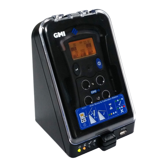
INTRODUCTION Fig. 1-1 PS500 Auto Bump / Calibration Station 1.1 GENERAL DESCRIPTION The PS500 Auto Bump / Calibration Station provides the user with a quick, easy and reliable method of ensuring that PS500 instruments are correctly calibrated where company policy dictates. - Page 12 AUTO BUMP / CALIBRATION STATION - USER HANDBOOK The Auto Bump / Calibration Station (ABC) has 3 variants: • Single gas unit (GMI part no. 61502) - 1 gas cylinder can be connected. • Multi-gas unit (GMI part no. 61504) - up to 3 gases cylinders can be connected.
- Page 13 INTRODUCTION The user simply inserts the PS500 into the ABC, then closes the cover initiating the automatic testing process. Note: The PS500 MUST be switched on before inserting into the Auto Bump / Calibration Station. The ABC uses a traffic light system to display progress / result, i.e.
- Page 14 ‘flexiCal Plus’ PC software package or the ‘IMS’ network software package, both available from GMI. Note: PS500 Bump / Calibration Software is only one part of the requirements in terms of calibration and maintenance of a PS500 portable gas detector.
-
Page 15: Auto Bump / Calibration Hardware
• USB memory stick with GMI ‘PS500 Settings’ software. 1.3 ADDITIONAL ACCESSORIES • Test Gas Cylinders - for a full list of gases, contact GMI or an authorised distributor. • On Demand Gas Flow Regulator - GMI Part No. 99118. - Page 16 AUTO BUMP / CALIBRATION STATION - USER HANDBOOK...
-
Page 17: Connect Calibration Gas And Power Supply
2.1 CONNECT CALIBRATION GAS Gas is supplied to the Auto Bump / Calibration Station from Test Gas Cylinders via On Demand Gas Flow Regulators (GMI Part No. 99118) and Tygon® tubing (GMI Part No. 12712). Fig. 2-1 Calibration Gas Setup... -
Page 18: Compare Gas Cylinder Label With Software Configuration
AUTO BUMP / CALIBRATION STATION - USER HANDBOOK 2.1.1 Compare Gas Cylinder Label with Software Configuration First of all, make sure that the cylinder is not older than the ‘use by’ date on the label illustrated in Fig. 2.2. Make sure that the cylinder contains enough gas to complete the bump test / calibration. - Page 19 CONNECT CALIBRATION GAS AND POWER SUPPLY The concentrations, illustrated in Fig. 2-2, should be consistent with the installed software configuration window, as illustrated in Fig. 2-3. Software Configuration - Gas Concentrations Fig. 2-3 Software Configuration After comparing gas values between the Cylinder Gas Label and the Software Configuration, when consistent, proceed to the next paragraph.
-
Page 20: Connect Gas Cylinder To Abc
AUTO BUMP / CALIBRATION STATION - USER HANDBOOK 2.1.2 Connect Gas Cylinder to ABC Connect the On Demand Regulator Valve to the gas cylinder by screwing the valve firmly into the top of the cylinder, as illustrated in Fig. 2-4. Fitting is simplified by pressing the valve on to the cylinder with one hand and turning the cylinder with the other. -
Page 21: Connect Air / Exhaust Tubing To Abc (If Required)
‘Exhaust’ outlet adaptors on the rear face of the ABC, using barbed adaptors. GMI recommend the use of an ‘Air’ in-line filter, also supplied with the unit. The (in-line filter) barbed adaptor is a push fit in the ‘Air’ inlet adaptor on the rear face of the ABC, as illustrated in Fig. - Page 22 AUTO BUMP / CALIBRATION STATION - USER HANDBOOK Fig. 2-6 Connect Air Tubing Adaptor to ABC The ‘Exhaust’ line, not illustrated, consists of a length of tubing and a barbed adaptor. The barbed adaptor is a push fit in the ‘Exhaust’ outlet adaptor on the rear face of the ABC. Exhaust tubing can be routed to the nearest window.
-
Page 23: Connect Power Supply
CONNECT CALIBRATION GAS AND POWER SUPPLY 2.2 CONNECT POWER SUPPLY Power is supplied to the ABC via a Universal AC Power Adaptor (12Vdc output) supplied with the unit. The plug adaptor is located in the 12Vdc socket on the rear face of the ABC, as illustrated in Fig. - Page 24 ‘ON’ indication illuminated, as shown in Fig. 2-8. Next, three LED’s coloured orange, orange and red illuminate briefly in sequence, indicating that GMI ‘TEST’ software has started. Finally, the ‘ON’ indication is illuminated, as illustrated in Fig.
-
Page 25: Software Configuration
ABC before testing / calibration can take place. To view ‘PS500 Settings’, insert the memory stick into an available USB port on your PC / Laptop. The following screen is displayed on a Windows 7™ PC / Laptop. - Page 26 Windows 7™. Select ‘Open folder to view files’ to display the contents, as illustrated in Fig. 3-2. Fig. 3-2 PS500 Settings Contents Folder Note: A short-cut to both the User Handbook and the Quick Operation Guide, can be accessed from this window.
- Page 27 • Test (i.e. bump test) • Calibration PS500 instruments can have many gas configurations. To incorporate the majority of gas configurations, there are two ABC type’s available for test and calibration: • Air + 1 gas. Single Gas Cylinder - Gas Input 1.
-
Page 28: Bump Test
AUTO BUMP / CALIBRATION STATION - USER HANDBOOK 3.1.1 Bump Test This feature provides the user with the ability to perform a full bump test, testing alarm set points and sensor response. When gas is applied, using Test Gas Cylinders, for a pre-set time, the audible and visual alarms will activate, and the unit... - Page 29 VIEW / RE-CONFIGURE SOFTWARE To enter / edit the gas concentration, highlight the gas value (0.0), then type in the new value (e.g. 50.0% LEL Methane), as illustrated in Fig. 3-5. Fig. 3-5 Gas Concentration Note: It is important that the ‘Gas Concentration’ value is consistent with the value displayed on the gas cylinder label.
-
Page 30: Calibration
AUTO BUMP / CALIBRATION STATION - USER HANDBOOK 3.1.2 Calibration This feature provides the user with the option of performing a full calibration of the instrument. When gas is applied, using Test Gas Cylinders, for a pre- set time, the audible and visual alarms will activate, and the unit will record a ‘Pass’... - Page 31 VIEW / RE-CONFIGURE SOFTWARE To enter / edit the gas concentration, highlight the gas value (0.0), then type in the new value (e.g. 50.0% LEL Methane), as illustrated in Fig. 3-8. Fig. 3-8 Gas Concentration Note: It is important that the ‘Gas Concentration’ value is consistent with the value displayed on the gas cylinder label.
-
Page 32: Generate Settings File
ABC. Fig. 3-9 Generate Setting Files To save changes, select the ‘Generate Settings File’ button to save the data to the USB memory stick. The message illustrated in Fig. 3-10 will be displayed. Fig. 3-10 New PS500 Settings File Generated... -
Page 33: Transfer Updated 'Ps500 Settings' To Abc
VIEW / RE-CONFIGURE SOFTWARE 3.2 TRANSFER UPDATED ‘PS500 SETTINGS’ to Make sure that the 12V power supply is connected to the ABC and switched ON, indicated by an illuminated green ‘ON’ LED on the front of the ABC and that the ABC has completed start-up. - Page 34 Fig. 3-13 Upload Complete Next, LED’s coloured orange, orange and red illuminate, as illustrated in Fig. 3-14 and GMI ‘TEST’ software has re- started. Fig. 3-14 Test Software Re-started Next, the three (orange, orange and red) LED’s extinguish, leaving only the green ‘ON’...
-
Page 35: Help Options
VIEW / RE-CONFIGURE SOFTWARE 3.3 HELP OPTIONS The ‘PS500 Settings’ software contains a Help menu, as illustrated in Fig. 3-15. Fig. 3-15 Help Menu The menu has the following options available: • Handbook - select to open the User Handbook (in PDF format). - Page 36 AUTO BUMP / CALIBRATION STATION - USER HANDBOOK 3-12...
-
Page 37: Bump / Calibration Operation
BUMP / CALIBRATION OPERATION 4.1 PS500 SWITCH ON The PS500 must be switched ON, before inserting into the Auto Bump / Calibration Station. To switch ON, press and hold the blue button, as illustrated in Fig. 4-1. Fig. 4-1 PS500 Switch ON... -
Page 38: Insert Instrument In Auto Bump / Calibration Station
4.2 INSERT INSTRUMENT IN AUTO BUMP / CALIBRATION STATION Note: Before use, ensure the ABC is ready for operation and the appropriate ‘PS500 Settings’ file has been transferred. To release the front cover of the Auto Bump / Calibration Station, press the cover latch downwards, as illustrated in Fig. - Page 39 BUMP / CALIBRATION OPERATION Locate the instrument inlet connector over the gas supply nozzle in the unit, as illustrated in Fig. 4-4. Fig. 4-4 Locate Instrument...
- Page 40 AUTO BUMP / CALIBRATION STATION - USER HANDBOOK Push the instrument rearwards until correctly seated in the station recess, as illustrated in Fig. 4-5. Fig. 4-5 Instrument Correctly Seated Note: Ensure the instrument is switched ON before closing the front cover.
- Page 41 BUMP / CALIBRATION OPERATION Close the front cover of the Auto Bump / Calibration Station, by using both thumbs. Press the lower centre of the cover firmly, as illustrated in Fig. 4-6, until the latch ‘clicks’ shut. Fig. 4-6 Close Front Cover...
-
Page 42: Bump / Calibration Operation
AUTO BUMP / CALIBRATION STATION - USER HANDBOOK 4.3 BUMP / CALIBRATION OPERATION The Bump / Calibration operation starts up automatically following the locking of the unit cover latch. After the cover latch ‘clicks’ shut, the orange ‘Test in Progress’ LED illuminates, as illustrated in Fig. -
Page 43: Remove Instrument From Abc
BUMP / CALIBRATION OPERATION Next, the unit pump switches OFF and the instrument can be safely removed. The test result indication is displayed until the door is opened. All test results are stored in the ABC memory and can be accessed as detailed in Chapter 5. -
Page 44: Abc Fault Indication
AUTO BUMP / CALIBRATION STATION - USER HANDBOOK CAUTION: Do not overextend angle of extraction as damage to the gas supply nozzle could result. Grasp the instrument, lean the top of instrument away from the ABC, then carefully lift away from gas supply nozzle, as illustrated in Fig. - Page 45 Auto Bump / Calibration Station inlet adaptor is inspected for possible restriction of blockage. If this action does not clear the fault, remove the instrument from the unit and inspect the instrument for possible flow fault. If this does not clear the fault, contact GMI.
- Page 46 AUTO BUMP / CALIBRATION STATION - USER HANDBOOK 4-10...
-
Page 47: View / Print Test Results
Fig. 5-1 Downloading Memory Stick The memory stick can be used to download data from several GMI Auto Bump / Calibration Stations, if required. The data identifies the serial number of the unit used to download data from each instrument, bump tested or calibrated. -
Page 48: Download Test Results
AUTO BUMP / CALIBRATION STATION - USER HANDBOOK 5.2 DOWNLOAD TEST RESULTS Make sure that the Auto Bump / Calibration Station is connected to mains power supply, switched ON and start-up is completed. This is indicated by an illuminated green ‘ON’ LED, on the front face of the unit, as illustrated in Fig. - Page 49 Next, LED’s coloured orange, orange and red illuminate, as illustrated in Fig. 5-6. This indicates that the test data has been downloaded and GMI ‘TEST’ software has re-started. Fig. 5-6 Test Software Re-started Next, the three (orange, orange and red) LED’s extinguish, leaving only the green ‘ON’...
-
Page 50: View / Print Test Results
Insert the USB memory stick into a USB port on PC / Laptop. Select ‘Open folder to view files’ to display the contents, as illustrated in Fig. 5-7. Fig. 5-7 PS500 Settings Contents Folder The contents of the folder are as follows: •... -
Page 51: Test Result Files
• • PS500 Settings application. • PS500 Settings.exe. Do not edit.# # - Depending on PC / Laptop ‘Folder Option’ settings these items may be hidden. If visible do not edit. 5.3.1 Test Result Files The contents of this folder includes all instrument test result files downloaded from each Auto Bump / Calibration Station that the USB memory stick has been used on. - Page 52 Each file can be opened individually to display a comprehensive list of test results obtained from that particular instrument. The following example, in Fig. 5-9, illustrates information available, including: • Instrument Type (e.g. PS500) • Test Type (e.g. CALIBRATION) • Instrument Serial No. (e.g. 250013) •...
- Page 53 VIEW / PRINT TEST RESULTS Fig.5-9 View Test Result File...
- Page 54 AUTO BUMP / CALIBRATION STATION - USER HANDBOOK Auto Bump / Calibration Station Instruments: The tested files (e.g. Tested805000.rec) illustrated in the Fig. 5-8, identifies the serial number of each Auto Bump / Calibration Station (e.g. 805000) that the memory stick has been used to download data from.
-
Page 55: Generated Certificates
VIEW / PRINT TEST RESULTS 5.3.2 Generated Certificates The contents of this folder includes a list of all Bump Test / Calibration Certificates generated when selecting the ‘View Certificate’ button in the configuration window, as illustrated in Fig. 5-11. Fig. 5-11 Configuration Window... - Page 56 AUTO BUMP / CALIBRATION STATION - USER HANDBOOK Certificate Content: The certificates, as illustrated in Fig. 5-17 and 5-18, include company details, order number, etc. These details are completed in a ‘Certificate Printer’ window, accessed by opening ‘View Certificate’ in the configuration window, illustrated in Fig.
- Page 57 ‘Generated Certificates’ folder on the memory stick. The logo will be included in the top right hand corner of the certificate, as illustrated in the ‘GMI’ logo example in the ‘Calibration Certificate’, illustrated in Fig. 5-18. Note: Logo dimensions must not exceed 200 (W) X 50 (H) pixels.
- Page 58 AUTO BUMP / CALIBRATION STATION - USER HANDBOOK After selecting the ‘Create Certificate’ button, the test results folder will be displayed, highlight a test result for certificate generation then select ‘Open’, as illustrated in Fig. 5-14. Fig. 5-14 Select Test Result for Certificate Generation Next, a ‘DONE!’...
- Page 59 VIEW / PRINT TEST RESULTS Generated Certificate Files The certificate files illustrated in Fig. 5-16, identifies date and time of each certificate’s generation. Fig. 5-16 Generated Certificate Files Each file can be opened individually to display / print a ‘Bump Results’...
- Page 60 AUTO BUMP / CALIBRATION STATION - USER HANDBOOK Fig. 5-17 Bump Results Fig. 5-18 Calibration Certificate 5-14...
-
Page 61: Fit Mounting Bracket
Fig. A-1 Auto Bump / Calibration Station (with mounting bracket fitted) 1. GENERAL DESCRIPTION The PS500 Auto Bump / Calibration Station is supplied with a mounting bracket and necessary screws to secure the unit to a workbench or similar. The bracket also provides the facility to ‘daisy chain’ a series... -
Page 62: Fit Mounting Bracket
AUTO BUMP / CALIBRATION STATION - USER HANDBOOK 2. FIT MOUNTING BRACKET Make sure the workbench surface is clean and free from dirt and grime. Place clean cloth or similar on workbench to protect Auto Bump / Calibration Station front cover surface from scratching and / or scuffing. -
Page 63: Attach Unit To Workbench / Daisy Chain Option
APPENDIX A Loosely attach two double sems pozi pan screws (Part No. 24957) through bracket and into rear panel of unit, as illustrated in Fig. A-2. Using a No.2 Pozidrive screwdriver, tighten all four screws to secure. 3. ATTACH UNIT to WORKBENCH / DAISY CHAIN OPTION The bracket can be secured to a workbench or similar type surface using four suitable screws (not supplied). - Page 64 AUTO BUMP / CALIBRATION STATION - USER HANDBOOK A group of Auto Bump / Calibration Stations can be connected in a ‘daisy chain’ fashion by using a double sems pozi pan screw supplied (Part No. 24957) through bracket at rear of station and into captive nut of adjoining bracket, as illustrated in Fig.
-
Page 65: Index
INDEX Symbols Bump Results 5-14 Bump Test 30 DAY LIMITED WARRANTY Calibration Calibration Certificate 5-14 About 3-11 Calibration Gas Setup Additional Accessories 1-5 Calibration Software Air + 1 gas Licence Air + 3 gas Certificate Completed 5-11 Air inlet Certificate Printer Air in-line filter Window 5-10... - Page 66 Fit Mounting Bracket Locate Instrument flexiCal Plus Mounting Bracket Gas Concentration 3-5, 3-7 Multi-gas unit Gas Cylinder Label Gas duration Gas inlet adaptor New PS500 Settings File General Description Generated Generated Certificate Normal Operating Files 5-13 Display Generated Certificates 5-9...
- Page 67 INFORMATION i, 1-3, 3-1, 5-1 Traffic light system PS500 Settings Transferring Data to Unit Contents Folder 3-2, 5-4 3-10 PS500 SWITCH ON Transfer Updated ‘PS500 Pump Fault Settings’ to ABC Tygon tubing 1-5, 2-1 Quick Operation Guide 3-11 Unit Loading Software Unit ‘ON’...
- Page 68 AUTO BUMP / CALIBRATION STATION - USER HANDBOOK...
- Page 70 Head Office Inchinnan Business Park Renfrew Scotland PA4 9RG Tel: +44 (0)141 812 3211 Fax: +44 (0)141 812 7820 sales@gmiuk.com www.gmiuk.com Service & Calibration Centre 25 Cochran Close Crownhill Milton Keynes MK8 0AJ Tel: +44 (0)1908 568 867 Fax: +44 (0)1908 261 056 service@gmiuk.com Service &...
Need help?
Do you have a question about the PS500 and is the answer not in the manual?
Questions and answers
ABC Dock for PS500: PS500 pump stops once the cover of the ABC Dock closes thus failing the bump/calibration. Pump should not be stop during the porcess.