Table of Contents
Advertisement
Available languages
Available languages
Quick Links
2024-05
Vers.: 2
Schaltgerät
Schaltgerät
Schaltgerät
Schaltgerät
Fettabscheider
Fettabscheider
Fettabscheider
Fettabscheider
Connect 400V Mono
Connect 400V Mono
Connect 400V Mono
Connect 400V Mono
Einbau- und Betriebsanleitung
Einbau- und Betriebsanleitung
Einbau- und Betriebsanleitung
Einbau- und Betriebsanleitung
DE
DE
Einbau- und Betriebsanleitung..........................2
Einbau- und Betriebsanleitung..........................2
EN
EN
Installation and operating instructions............ 21
Installation and operating instructions............ 21
FR
FR
Instructions de pose et d'utilisation.................40
Instructions de pose et d'utilisation.................40
IT
IT
Istruzioni per l'installazione e l'uso................. 59
Istruzioni per l'installazione e l'uso................. 59
NL
NL
Inbouw- en bedieningshandleiding................. 78
Inbouw- en bedieningshandleiding................. 78
PL
PL
Instrukcja zabudowy i obsługi......................... 97
Instrukcja zabudowy i obsługi......................... 97
016-271
Advertisement
Chapters
Table of Contents

Subscribe to Our Youtube Channel
Related Manuals for Kessel Connect 400V Mono


Summary of Contents for Kessel Connect 400V Mono
- Page 1 Schaltgerät Schaltgerät Schaltgerät Schaltgerät Fettabscheider Fettabscheider Fettabscheider Fettabscheider Connect 400V Mono Connect 400V Mono Connect 400V Mono Connect 400V Mono Einbau- und Betriebsanleitung Einbau- und Betriebsanleitung Einbau- und Betriebsanleitung Einbau- und Betriebsanleitung Einbau- und Betriebsanleitung......2 Einbau- und Betriebsanleitung......2 Installation and operating instructions.... 21 Installation and operating instructions....
-
Page 2: Table Of Contents
Produkte, sondern auch im Hinblick auf deren langfristigen Betrieb setzen wir uns dafür ein, dass Sie und Ihr Eigentum Montage..............dauerhaft geschützt sind. Betrieb..............Ihre KESSEL SE + Co. KG Konformitätserklärung - Declaration of Conformity.. 116 Bahnhofstraße 31 85101 Lenting, Deutschland Bei technischen Fragestellungen helfen Ihnen gerne unsere qualifizierten Servicepartner vor Ort weiter. -
Page 3: Hinweise Zu Dieser Anleitung
Folgende Symbole werden verwendet: Hinweise zu dieser Anleitung Zeichen Bedeutung Bei diesem Dokument handelt es sich um die Originalbe- triebsanleitung. Die Sprache der Originalbetriebsanleitung ist Gerät freischalten! Deutsch. Alle weiteren Sprachen dieser Anleitung sind eine Übersetzung der Originalbetriebsanleitung. Folgende Darstellungskonventionen erleichtern die Ori- Gebrauchsanweisung beachten entierung: Darstellung... -
Page 4: Sicherheit
Der Betreiber der Anlage ist dazu verpflichtet: eine Gefährdungsbeurteilung zu erstellen, entsprechende Gefährdungszonen zu ermitteln und aus- zuweisen, Sicherheitsunterweisungen durchzuführen, gegen die Benutzung durch Unbefugte zu sichern. Person freigegebene Tätigkeiten an KESSEL-Anlagen Betreiber Sichtprüfung, Inspektion Sachkundiger (kennt, ver- Funktionskontrolle, Konfi- steht Betriebsanweisung) guration des Schaltgerätes... - Page 5 Produkt verfügbar gehalten werden. den Tausch der Batterien, das Anschließen nach Einbauanleitung und Anschlussplan beschränkt. Alle darüber hinausgehenden Arbeiten dürfen ledig- lich durch den KESSEL-Kundendienst oder einen Servicepartner der KESSEL SE + Co. KG durchge- führt werden. 5 / 120...
- Page 6 Bestimmungsgemäße Verwendung Das Schaltgerät stellt die Steuerung einer Anlage zum Abscheiden von Fett aus häuslichem oder gewerblichem Abwasser gemäß DIN EN 1825. Die Programmierung des Schaltgerätes erfolgt über eine App. WARNUNG Das Schaltgerät selbst ist NICHT für den Einbau in einer EX-Zone vorgesehen! Alle nicht vom Hersteller ausdrücklich und schriftlich autorisierten: Um- oder Anbauten Verwendungen von nicht originalen Ersatzteilen...
- Page 7 Hinweise zur Positionierung von Freiluftsäulen WARNUNG Bei Überschreiten den maximal zulässigen Betriebstemperatur kann zu einer Störung des Schaltgerätes führen. Aufstellort der Freiluftsäule berücksichtigen Die Sonneneinwirkung am Aufstellort bewerten. Umgebungsbedingungen vor Ort hinzuziehen. Die folgende Tabelle gibt einen Überblick über die erforderlichen Maßnahmen. Regelmäßige, starke Sonneneinwir- Montage eines Kühlgerätesets für Freiluftsäulen (Art.-Nr.
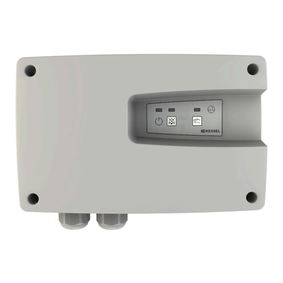
- Page 8 Baugruppen- und Funktionsübersicht Anzeigen, Bedientasten und deren Funktionen Anschluss für Pumpe(n) LED Betriebsbereit (grün) Netzanschlussleitung LED Alarm (rot) Blindstopfen, optionale Anschlüsse LED Motor/Pumpe läuft (orange) Typenschild Symbol Betrieb LEDs und Bedienfeld Taste Alarm ausschalten (quittieren) Taste Motor/Pumpe ein (manuell) 8 / 120...
-
Page 9: Technische Daten
Technische Daten Angabe Spezifikation Maximale Leistung (kW) am Schaltausgang (bei cos φ = 1) Nennstrombereich 2,5 - 6 A Gewicht 1 kg Abmessungen (LxBxT), mm 234x184x75 Betriebsspannung 400 V / 50 Hz Leistung, Standby Potentialfreier Kontakt max. 42 V DC / 0,5 A Einsatztemperatur 0 - 50°C Relative Luftfeuchtigkeit [%] (nicht kondensierend) -
Page 10: Montage
Schaltgerät montieren und leicht nach unten drücken. L = 208mm Das Schaltgerät ist ausschließlich für die Innenmon- tage oder Montage in einer KESSEL Freiluftsäule bestimmt. Es darf keiner direkten Sonneneinstrahlung ausgesetzt werden und muss in einer trockenen, gut belüfteten und frostfreien Umgebung installiert werden. - Page 11 Elektrischer Anschluss GEFAHR Gefahr durch falsch dimensionierte Anschlussleitun- gen. Für alle Anschlüsse und Installations-Arbeiten an der Anlage gelten nationale Vorschriften zur elektri- schen Sicherheit. Die Anschlusskabel sicher vom Anlagenbehälter zum Schaltgerät verlegen (z. B. Kabelleerrohr). Ausreichend Kabellänge für die Wartung der elektrischen Komponen- ten vorhalten.
- Page 12 4.2.1 Anschlussplan 12 / 120...
-
Page 13: Betrieb
Die Anlage befindet sich im Bereitschaftsmodus, wenn kein Fehler erkannt wurde und die Betriebs-LED (1) grün leuchtet. Wird das Schaltgerät als Ersatzteil bezogen, ist dieses auf die kürzeste Laufzeit (96s) eingestellt. Die Laufzeit kann mit der KESSEL App angepasst werden. Laufzeiten siehe "Funktionsprüfung (EasyClean free Mix)", Seite 14 und siehe "Funktionsprüfung (EasyClean free Mix&Pump)", Seite 15. - Page 14 Die Werte können mit der KESSEL NFC App an die 5.1.1 Funktionsprüfung (EasyClean free Mix) jeweiligen Erfordernissen angepasst werden siehe "Kapi- Funktionsprüfung Schredder-Mix Pumpe tel Betrieb - Daten auslesen und Parameter einstellen", Sicherstellen, dass sich der Absperrschieber für das Pum- Seite 19.
- Page 15 Die Werte können mit der KESSEL NFC App an die 5.1.2 Funktionsprüfung (EasyClean free Mix&Pump) jeweiligen Erfordernissen angepasst werden siehe "Kapi- Funktionsprüfung Schredder-Mix Pumpe tel Betrieb - Daten auslesen und Parameter einstellen", Sicherstellen, dass sich der Absperrschieber für das Pum- Seite 19.
- Page 16 Übersicht LED-Anzeigen - Informationen Blinkmuster LED 1 - 3 Blinken Leuchten / Eingeschaltet Ausgeschaltet Betriebszustände Signalton Beschreibung Maßnahme (Intervall) grün (1) rot (2) orange (3) Außer Betrieb, keine Netzspannung Batterieüberwachung wiederherstellen 16 / 120...
- Page 17 Signalton Beschreibung Maßnahme (Intervall) grün (1) rot (2) orange (3) Betriebsbereit Potentialfreier Kontakt wird aktiviert. Die Batterieüberwachung ist nur aktiv, wenn bei Inbetriebnahme eine Batterie angeschlossen war. Alarmzustände / Fehler Signalton Beschreibung Maßnahme (Intervall) grün (1) rot (2) orange (3) Netzausfall, Netzspannung Netzspannung wieder her- fehlt, Anlage ohne Funktion...
- Page 18 Leuchten der LED Alarm (rot / 2) und ggf. einer der anderen LEDs angezeigt. Nach der Beseitigung der Ursache für den Alarm, kann der Alarm durch Drücken der Taste (5) quittiert werden. Die Fehlermeldungen können über die KESSEL NFC-App ausgelesen werden. Download in den App-Stores. Alarmton ausschalten Taste (5) 1x drücken...
- Page 19 Daten auslesen und Parameter einstellen Mit der KESSEL NFC App und einem NFC fähigen Endgerät (z.B. Mobiltelefon) ist es möglich das Logbuch des Schaltgerä- tes auszulesen, Datum und Uhrzeit zu synchronisieren und diverse Parameter anzupassen. WARNUNG Vor Benutzung der App ist das Schaltgerät in Betrieb zu nehmen siehe "Kapitel Betrieb", Seite 13.
- Page 20 Abb.: Endgerät - Smartphone Schaltgerät lesen Dazu muss sich das NFC fähig Endgerät direkt am Schaltgerät befinden ("Abb. Endgerät-Smarthphone"). Parameter anzeigen und bearbeiten: Diese können kopiert und per Email versendet werden. (Passwort 1000) Datum/Uhrzeit synchronisieren Werte von NFC fähigem Gerät auf das Schaltgerät übertragen. 20 / 120...
- Page 21 Installation and operating instructions As a premium manufacturer of innovative products for drain- Contents ing technology, KESSEL offers integrated system solutions and customer-oriented service. In doing so, we set the high- Notes on this manual..........est quality standards and focus firmly on sustainability - not Safety...............
-
Page 22: Installation And Operating Instructions
The following symbols are used: Notes on this manual Icon Meaning This document is a translation of the original operating instructions. The original operating instructions are written Isolate device! in German. All other language versions of these instructions are a translation of the original operating instructions. The following conventions make it easier to navigate the Observe the instructions for use manual:... -
Page 23: Safety
The operator of the system must: prepare a risk assessment identify and demarcate corresponding hazard zones carry out safety training secure the system against unauthorised use. Person Approved activities on KESSEL systems Operating company Visual inspec- tion, inspection Technical expert, (familiar with, Functional check, config-... - Page 24 Connection in accordance with the installation instructions and wiring diagram. All work extending beyond this may only be carried out by KESSEL customer service or a KESSEL SE + Co. KG service partner. WARNING Live parts Heed the following points when working on electrical cables and connections.
- Page 25 Intended use The control unit is the control of a system for separating grease from domestic or commercial wastewater according to EN 1825. The control unit is programmed via an app. WARNING The control unit itself is NOT intended for installation in an EX zone! All: modifications or attachments use of non-genuine spare parts...
- Page 26 Notes on positioning outdoor cabinets WARNING Exceeding of the maximum permissible operating temperature can lead to a fault in the control unit. Take into consideration the place in which the outdoor cabinet is installed Evaluate the sunshine at the installation site. Take into account the ambient conditions on site.
- Page 27 Assemblies and functional overview Displays, operating keys and their functions Connection for pump(s) Ready for operation LED (green) Mains cable Alarm LED (red) Blind plug, optional connections Motor/pump running LED (orange) Type plate Operation symbol LEDs and control panel Switch off (acknowledge) alarm button Motor/pump on (manual) button Installation and operating instructions 27 / 120...
-
Page 28: Technical Data
Technical data Item Specification Maximum power (kW) at the switch output (if cos φ = 1) Nominal current range 2.5 - 6 A Weight 1 kg Dimensions (LxWxD), mm 234x184x75 Operating voltage 400 V / 50 Hz Standby power Potential-free contact max. -
Page 29: Installation
L = 208 mm The control unit is solely intended for indoor installation or installation in a KESSEL outdoor cabinet. It must not be exposed to direct sunshine and must be installed in a dry, well-ventilated and frost-free environ- ment. - Page 30 Electrical connection DANGER Danger through incorrectly dimensioned connection cables. The national regulations concerning electrical safety apply to all connections and installation work. Lay the connection cable safely (e.g. cable duct) from the system tank to the control unit. Ensure that there is ade- quate cable length for the maintenance of the electrical components.
- Page 31 4.2.1 Connection diagram Installation and operating instructions 31 / 120...
-
Page 32: Operation
If the control unit is purchased as a replacement part, it is set to the shortest running time (96 sec). The running time can be adjusted using the KESSEL app. Running times see "Functional test (EasyClean free Mix)", page 33 and see "Functional test (EasyClean free Mix&Pump)", page 34. - Page 33 The values can be adjusted to the respective require- 5.1.1 Functional test (EasyClean free Mix) ments using the KESSEL NFC app. see "Operation chap- Functional test shredder-mix pump ter - Data read-out and parameter setting", page 38. Make sure that the shut-off valve for the pump valve is Download it from the app stores.
- Page 34 The values can be adjusted to the respective require- 5.1.2 Functional test (EasyClean free Mix&Pump) ments using the KESSEL NFC app. see "Operation chap- Functional test shredder-mix pump ter - Data read-out and parameter setting", page 38. Make sure that the shut-off valve for the pump valve is Download it from the app stores.
- Page 35 Overview of LED displays - Information Flashing pattern LED 1 - 3 Flashing Lights up / switched on Switched off Operating states Acoustic signal Description Measure (interval) Green Red (2) Orange (3) Out of service, no Restore the mains voltage battery monitoring Installation and operating instructions 35 / 120...
- Page 36 Acoustic signal Description Measure (interval) Green Red (2) Orange (3) Ready for operation Potential-free contact is activated. The battery monitoring is only active if a battery was connected at the time of commissioning. Alarm statuses / errors Acoustic signal Description Measure (interval) Green...
- Page 37 LED (red/2) and, if applicable, one of the other LEDs. After rectifying the cause of the alarm, the alarm can be acknowledged by pressing the button (5). The error messages can be read out via the KESSEL NFC app. Download it from the app stores.
- Page 38 Data read-out and parameter setting It is possible to read out the log book of the control unit with the KESSEL NFC app and an NFC-capable end device (e.g. mobile phone), to synchronise the date and time and to adjust various parameters.
- Page 39 Fig.: End device - smartphone Read the control unit To do this, the NFC-capable end device must be located directly on the control unit ("Fig. End device - smartphone"). Display and edit parameters: These can be copied and sent by email. (Password 1000) Synchronise the date/time Transfer values from the NFC-capable device to the control unit.
-
Page 40: Bahnhofstraße
Instructions de pose et d’utilisation En qualité de producteur de pointe de produits novateurs Sommaire dans le domaine de la technique d’assainissement, KESSEL propose des réponses systématiques globales et un ser- Informations spécifiques aux présentes instruc- vice orienté aux besoins de la clientèle. Nous misons simul- tions................. -
Page 41: Instructions De Pose Et D'utilisation
Informations spécifiques aux Représentation Explication présentes instructions informations techniques à observer en particulier. Ce document est la traduction de l'original du mode d’em- Les instructions emploient les pictogrammes suivants : ploi. L’original a été rédigé en allemand. Toutes les autres Picto- versions linguistiques de ce mode d’emploi sont des traduc- gramme /... -
Page 42: Sécurité
à la mise en pratique de formations se rappor- tant aux consignes de sécurité, de le protéger contre l’utilisation par des personnes non autorisées. Personne Activités autorisées sur les systèmes KESSEL Exploitant Contrôle visuel, inspection Technicien spécialisé (connaît et com- Contrôle fonctionnel, confi-... - Page 43 Tous les travaux dépassant ce cadre sont réservés au domaine de compétence du service après-vente KESSEL ou d'un partenaire du service après-vente de KESSEL SE + Co. KG. Instructions de pose et d’utilisation...
- Page 44 Utilisation conforme à l'usage prévu Le gestionnaire permet de commander un poste permettant de séparer la graisse des eaux usées domestiques ou indus- trielles conformément à la norme DIN EN 1825. La programmation du gestionnaire se fait via une appli. AVERTISSEMENT Le gestionnaire en soi N’EST PAS prévu pour un montage dans une zone EX ! Toutes les interventions non expressément autorisées par écrit par le fabricant, notamment les...
- Page 45 Remarques concernant le positionnement des armoires électriques extérieures AVERTISSEMENT Tout dépassement de la température de service maximale autorisée peut entraîner un dysfonctionnement du ges- tionnaire. Tenir compte de l’emplacement de montage de l'armoire électrique extérieure Évaluer l’exposition au soleil sur l’emplacement de montage. Consulter les conditions ambiantes sur site.
- Page 46 Aperçu des sous-groupes et des fonctions Affichages, touches de commande et leurs fonctions Raccord pour pompe(s) Câble d'alimentation Voyant état opérationnel (vert) Bouchons, raccords optionnels Voyant d’alarme (rouge) Plaque signalétique Voyant moteur/pompe en marche (orange) Voyants et panneau de commande Pictogramme En service Touche extinction de l'alarme (acquittement) Touche activation moteur/pompe (manuelle)
-
Page 47: Caractéristiques Techniques
Caractéristiques techniques Indication Spécification Puissance maximale (kW) à la sortie de commutation (pour cos φ = 1) Plage de courant nominal 2,5 à 6 A Poids 1 kg Dimensions (LxlxH), mm 234 x 184 x 75 Tension de service 400 volts / 50 Hz Puissance en veille Contact sec maximum 42 volts CC / 0,5 A... -
Page 48: Montage
L = 208mm Le gestionnaire est exclusivement destiné à un mon- tage en intérieur ou dans une armoire électrique exté- rieure KESSEL. Il ne doit pas être exposé aux rayons directs du soleil et doit être installé dans un environnement sec, bien aéré... - Page 49 Raccordement électrique DANGER Risque dû au dimensionnement erroné des conduites de raccordement. Les directives nationales de sécurité électrique s’ap- pliquent à tous les raccordements et travaux d’ins- tallation sur le système. Poser les câbles de raccordement correctement de la cuve jusqu'au gestionnaire (se servir par ex. d'un four- reau pour câbles).
- Page 50 4.2.1 Schéma de raccordement 50 / 120 Instructions de pose et d’utilisation...
-
Page 51: Fonctionnement
Si le gestionnaire est acheté en tant que pièce de rechange, celui-ci est paramétré sur la durée de fonctionnement la plus courte (96s). Il est possible de modifier la durée de fonctionnement avec l’appli KESSEL. Durées de fonctionnement cf. "Contrôle fonctionnel (EasyClean free Mix)", page 52 et cf. "Contrôle fonctionnel (Easy- Clean free Mix&Pump)", page 53. - Page 52 Les valeurs peuvent être adaptées aux différentes exi- 5.1.1 Contrôle fonctionnel (EasyClean free Mix) gences via l’appli NFC de KESSEL. cf. "Chapitre Fonc- Contrôle fonctionnel de la pompe Schredder-Mix tionnement - Lire les données et régler les paramètres", S'assurer que le dispositif d’arrêt pour la vanne de pompe page 57.
- Page 53 Les valeurs peuvent être adaptées aux différentes exi- 5.1.2 Contrôle fonctionnel (EasyClean free Mix&Pump) gences via l’appli NFC de KESSEL. cf. "Chapitre Fonc- Contrôle fonctionnel de la pompe Schredder-Mix tionnement - Lire les données et régler les paramètres", S'assurer que le dispositif d’arrêt pour la vanne de pompe page 57.
- Page 54 Aperçu des voyants d'affichage - informations Motif de clignotement des voyants 1 - 3 Clignotent S'allument / activées Désactivées États de service Diode Signal Contact sonore Description Action (intervalle) rouge vert (1) orange (3) Hors service, pas de sur- Rétablir la tension de réseau veillance de la batterie 54 / 120 Instructions de pose et d’utilisation...
- Page 55 Diode Signal Contact sonore Description Action (intervalle) rouge vert (1) orange (3) Prêt à fonctionner Le contact sec est activé. La surveillance de la batterie n’est active que si une batterie a été raccordée lors de la mise en service. États d'alarme / erreurs Diode Signal...
- Page 56 Éliminer la cause de l'alarme, puis acquitter l'alarme en appuyant sur la touche (5). Il est possible de consulter les messages d’erreur via l’ap- pli NFC de KESSEL. Téléchargement dans l’App Store. Désactivation de l'alarme acoustique Appuyer 1 fois sur la touche (5) Acquittement de l'alarme Maintenir la touche (5) enfoncée pendant plus de 3...
- Page 57 Lire les données et régler les paramètres Il est possible de consulter le journal d'exploitation du gestionnaire, de synchroniser la date et l'heure et d'ajuster divers paramètres avec l’appli NFC de KESSEL et avec un terminal compatible NFC (par ex. téléphone portable). AVERTISSEMENT Mettre le gestionnaire en service avant d'utiliser l’appli cf.
- Page 58 Fig.: Terminal - Smartphone Consulter les données du gestionnaire Pour cela, le terminal compatible NFC doit se trouver directement au niveau du gestionnaire ("fig. Terminal-Smartphone"). Afficher et éditer les paramètres : Ceux-ci peuvent être copiés et envoyés par mail. (mot de passe 1000) Synchroniser la date/l’heure Transférer les valeurs de l’appareil compatible NFC au gestionnaire.
- Page 59 Istruzioni per l’installazione e l’uso in qualità di produttore premium di prodotti innovativi per la Indice tecnica di drenaggio, KESSEL offre soluzioni di sistema inte- grate e un servizio orientato al cliente. Puntiamo sui mas- Indicazioni sulle presenti istruzioni......simi standard qualitativi e ci impegniamo coerentemente per Sicurezza..............
-
Page 60: Istruzioni Per L'installazione E L'uso
Indicazioni sulle presenti istruzioni Simbolo Spiegazione Avvertenza tecnica che Il presente documento costituisce le istruzioni per l’uso origi- richiede particolare attenzione. nali. La lingua delle istruzioni per l’uso originali è il tedesco. Sono impiegati i simboli seguenti: Tutte le versioni in altre lingue di queste istruzioni costitui- scono delle traduzioni. -
Page 61: Sicurezza
Persona Mansioni ammesse sugli impianti KESSEL Esercente Controllo visivo, ispezione Esperto (conosce e com- Controllo del funzionamento, prende le istruzioni per l’uso) - Page 62 Tutti i lavori diversi da quelli elencati devono essere eseguiti esclusivamente dal servizio clienti KESSEL o da un partner di assistenza della KESSEL SE + Co. KG. 62 / 120 Istruzioni per l’installazione e l’uso...
- Page 63 Uso conforme alla destinazione La centralina rappresenta il comando di un impianto per la separazione dei grassi dalle acque di scarico domestiche o com- merciali a norma DIN EN 1825. La programmazione della centralina avviene tramite un’app. AVVERTENZA La centralina in quanto tale NON è pensata per l’installazione in una zona potenzialmente esplosiva! Tutte le operazioni elencate di seguito non espressamente autorizzate per iscritto dal produttore: Le modifiche e le aggiunte Gli impieghi di ricambi non originali...
- Page 64 Indicazioni per il posizionamento delle cabine esterne per quadro elettrico AVVERTENZA In caso di superamento della temperatura di funzionamento massima ammessa può verificarsi un disturbo alla cen- tralina. Considerare il luogo di montaggio dalla cabina esterna per quadro elettrico Valutare l’influsso del sole nel luogo di montaggio. Tenere in considerazione le condizioni ambientali locali.
- Page 65 Gruppi costruttivi e visione d’insieme del Visualizzazioni, tasti di comando e loro funzioni funzionamento LED Prontezza al funzionamento (verde) Collegamento per pompa/e LED di allarme (rosso) LED motore/pompa in funzione (arancio) Cavo di alimentazione Tappo cieco, collegamenti opzionali Simbolo di funzionamento Tasto di spegnimento dell’allarme (conferma) Targhetta LED e quadro di comando...
-
Page 66: Dati Tecnici
Dati tecnici Indicazione Specifica Potenza massima (kW) all’uscita di commutazione (con cos φ = 1) Gamma di corrente nominale 2,5 - 6 A Peso 1 kg Dimensioni (Lu x La x Pr), mm 234x184x75 Tensione di funzionamento 400 V / 50 Hz Potenza, stand-by Contatto a potenziale zero max. -
Page 67: Montaggio
L = 208 mm La centralina è progettata esclusivamente per il mon- taggio all’interno o per il montaggio in una cabina esterna per quadro elettrico KESSEL. Non deve essere esposta all’irraggiamento solare diretto e deve essere installata in un ambiente asciutto, ben ventilato e protetto dal gelo. - Page 68 Collegamento elettrico PERICOLO Pericolo a causa del dimensionamento errato dei condotti di collegamento. Per tutti i lavori di collegamento e installazione sull’impianto trovano applicazione le norme nazio- nali sulla sicurezza elettrica. Posare il cavo di collegamento in modo sicuro dal ser- batoio alla centralina (ad esempio attraverso il tubo per cavi).
- Page 69 4.2.1 Schema di collegamento Istruzioni per l’installazione e l’uso 69 / 120...
-
Page 70: Funzionamento
Se la centralina è acquistata come pezzo di ricambio, questa è impostata sulla durata di funzionamento più breve (96s). La durata di funzionamento può essere modificata con l’app KESSEL. Durate di funzionamento vd. "Verifica del funzionamento (EasyClean free Mix)", pagina 71 e vd. "Verifica del funziona- mento (EasyClean free Mix&Pump)", pagina 72. - Page 71 I valori possono essere adeguati alle rispettive esi- 5.1.1 Verifica del funzionamento (EasyClean free Mix) genze con l’app KESSEL NFC vd. "Capitolo Funziona- Verifica del funzionamento della pompa Schredder-Mix mento - Lettura dei dati e impostazione dei parametri", Accertare che la paletta di chiusura per la valvola della pagina 76.
- Page 72 I valori possono essere adeguati alle rispettive esi- Verifica del funzionamento della pompa Schredder-Mix genze con l’app KESSEL NFC vd. "Capitolo Funziona- Accertare che la paletta di chiusura per la valvola della mento - Lettura dei dati e impostazione dei parametri", pompa si trovi in posizione aperta (completamente pagina 76.
- Page 73 Visione d’insieme degli indicatori LED – Informazioni Schema di lampeggio LED 1 – 3 Lampeggiante Illuminato / Acceso Spento Stati di funzionamento Segnale acustico Descrizione Misura (intervallo) rosso verde (1) arancio (3) Fuori servizio, nessun moni- Ripristinare la ten- toraggio della batteria sione di rete elettrica Istruzioni per l’installazione e l’uso 73 / 120...
- Page 74 Segnale acustico Descrizione Misura (intervallo) rosso verde (1) arancio (3) Condizione di prontezza per il funzionamento Il contatto a potenziale zero viene attivato. Il monitoraggio batteria è attivo solo se al momento della messa in funzione è stata collegata una batteria. Stati di allarme / Errori Segnale acustico...
- Page 75 LED. Dopo l’eliminazione della causa dell’allarme, l’allarme potrà essere confermato con la pressione del tasto (5). I messaggi di errore possono essere letti con l’app NFC KESSEL. scaricabile dagli app store. Spegnimento del segnale acustico d’allarme Premere il tasto (5) 1 volta Conferma dell’allarme...
- Page 76 Lettura dei dati e impostazione dei parametri Con l’app KESSEL NFC e un dispositivo terminale abilitato alla NFC (ad esempio un telefono cellulare) è possibile leggere il diario d’esercizio della centralina, sincronizzare la data e l’ora e modificare diversi parametri.
- Page 77 Fig.: Dispositivo terminale – smartphone Lettura della centralina Per questa operazione, il dispositivo terminale abilitato alla NFC deve trovarsi direttamente presso la centralina ("figura Dispositivo terminale – smartphone"). Visualizzazione e modifica dei parametri: Questi possono essere copiati e inviati via e-mail. (Password 1000) Sincronizzazione di data/ora Trasmissione dei dati dal dispositivo abilitato alla NFC alla centralina.
-
Page 78: Kessel Se + Co. Kg Bahnhofstraße
Beste klant, Inbouw- en bedieningshandleiding Als premium fabrikant van innovatieve producten voor de Inhoud afwateringstechniek biedt KESSEL totale systeemoplossin- gen en klantgerichte service. Wij stellen hierbij maximale Informatie over deze handleiding......kwaliteitsnormen en zetten consequent in op duurzaamheid, Veiligheid..............niet alleen bij de productie van onze producten, maar ook Technische gegevens.......... -
Page 79: Inbouw- En Bedieningshandleiding
De volgende symbolen worden gebruikt: Informatie over deze handleiding Teken Betekenis Dit document bevat de originele bedieningshandleiding. De handleiding is in het Duits geschreven. Alle teksten in andere Schakel het apparaat vrij! talen in deze handleiding zijn vertalingen van de oorspronke- lijke Duitse tekst. -
Page 80: Veiligheid
De exploitant van de installatie is verplicht tot: het maken van een risicobeoordeling, het vaststellen en aantonen van gevarenzones, het uitvoeren van veiligheidsinstructies, het beveiligen tegen gebruik door onbevoegden. Persoon Vrijgegeven werkzaamheden bij KESSEL-installaties Exploitant Visuele con- trole, inspectie Deskundige (kent, begrijpt gebruiksaanwijzing) Functiecontrole, configura-... - Page 81 Alle verdergaande werkzaamheden mogen enkel door de KESSEL-klantenservice of een servicepart- ner van KESSEL SE + Co. KG worden uitgevoerd. Inbouw- en bedieningshandleiding 81 / 120...
- Page 82 Beoogd gebruik De besturingskast bestuurt een installatie voor het afscheiden van vet uit huishoudelijk of industrieel afvalwater conform DIN EN 1825. De besturingskast wordt met een app geprogrammeerd. WAARSCHUWING De besturingskast zelf is NIET bedoeld voor inbouw in een EX-zone! Alle niet expliciet en schriftelijk door de fabrikant toegestane: om- of aanbouw gebruik van niet-originele onderdelen...
- Page 83 Advies voor het plaatsen van buitenkasten WAARSCHUWING Het overschrijden van de maximaal toegestane bedrijfstemperatuur kan leiden tot een storing in de besturingskast. Houd rekening met de locatie van de buitenkast De invloed van zonlicht op de opstellocatie schatten. Lokale omgevingsomstandigheden in de schatting meenemen. In de volgende tabel vindt u een overzicht van de vereiste maatregelen.
- Page 84 Module- en functieoverzicht Indicaties, besturingstoetsen en hun functies Aansluiting voor pomp(en) Bedrijfsklaar (groene led) Netaansluitkabel Alarm (rode led) Blindstoppen, optionele aansluitingen Motor/pomp draait (oranje led) Typeplaatje Symbool in bedrijf Leds voor bediening Toets alarm uitschakelen (resetten) Toets motor/pomp inschakelen (handmatig) 84 / 120 Inbouw- en bedieningshandleiding...
-
Page 85: Technische Gegevens
Technische gegevens Opgave Specificatie Maximaal vermogen (kW) bij uitgang schakelaar (bij cos. φ = 1) Nominaal stroombereik 2,5 – 6 A Gewicht 1 kg Afmetingen (lxbxd), mm 234x184x75 Bedrijfsspanning 400 V / 50 Hz Vermogen, stand-by Potentiaalvrij contact max. 42 V DC / 0,5 A Gebruikstemperatuur 0 –... -
Page 86: Monteren
L = 208 mm De besturingskast is alleen bedoeld voor montage bin- nenshuis of in een KESSEL-buitenkast. Hij mag niet worden blootgesteld aan direct zonlicht en moet in een droge, goed geventileerde en vorstvrije omgeving worden geïnstalleerd. - Page 87 Elektrische aansluiting GEVAAR Gevaar door foutief gedimensioneerd leidingwerk. Voor alle aansluitingen en installatiewerkzaamhe- den aan de installatie gelden nationale voorschriften voor elektrische veiligheid. Leg de aansluitkabels correct van het reservoir naar de besturingskast (bijv. met een mantelbuis). Zorg dat er vol- doende kabellengte is voor het onderhoud aan elektri- sche onderdelen.
- Page 88 4.2.1 Aansluitschema 88 / 120 Inbouw- en bedieningshandleiding...
-
Page 89: Gebruik
Als de besturingskast als reserveonderdeel wordt aangeschaft, dan is hij ingesteld op de kortste looptijd (96 s). De loop- tijd kan met de KESSEL-app worden aangepast. Looptijden zie "Functiecontrole (EasyClean free Mix)", pagina 90 en zie "Functiecontrole (EasyClean free Mix &... - Page 90 De waarden kunnen met de Kessel-NFC-app aan de toe- 5.1.1 Functiecontrole (EasyClean free Mix) passelijke eisen worden aangepast zie "Hoofdstuk Bedie- Functiecontrole Schredder-mix-pomp ning, paragraaf Gegevens uitlezen en parameters instel- Zorg dat de afsluiter van het pompventiel zich in de geo- len", pagina 95.
- Page 91 Functiecontrole (EasyClean free Mix & Pump) NG15/NG20: elk 624 seconden Functiecontrole Schredder-mix-pomp De waarden kunnen met de Kessel-NFC-app aan de toe- Zorg dat de afsluiter van het pompventiel zich in de geo- passelijke eisen worden aangepast zie "Hoofdstuk Bedie- pende stand bevindt (volledig uitgetrokken en vergren- ning, paragraaf Gegevens uitlezen en parameters instel- deld).
- Page 92 Overzicht van ledaanduidingen/informatie Knipperpatroon leds 1 – 3 Knipperen Branden/ingeschakeld Uitgeschakeld Bedrijfstoestanden Waarschu- wings- Omschrijving Maatregel signaal (interval) groen rood oranje (3) Buiten bedrijf, geen Netspanning herstellen batterijbewaking 92 / 120 Inbouw- en bedieningshandleiding...
- Page 93 Waarschu- wings- Omschrijving Maatregel signaal (interval) groen rood oranje (3) Bedrijfsklaar Het potentiaalvrij contact wordt geactiveerd. De accubewaking is alleen actief als tijdens de inbedrijfstelling een accu was aangesloten. Alarmtoestanden/storing Waarschu- wings- Omschrijving Maatregel signaal (interval) groen rood oranje (3) Stroomstoring, net- Netspanning herstel- spanning ontbreekt,...
- Page 94 Na het opheffen van de oorzaak voor het alarm kan het alarm worden gereset door het indrukken van de toets (5). De foutmeldingen kunnen in de KESSEL-NFC-app wor- den bekeken. De app kan uit de appwinkels worden gedownload.
- Page 95 Gegevens uitlezen en parameters instellen Met de KESSEL NFC-app en een apparaat met NFC-ondersteuning (bijv. een mobiele telefoon) kan het logboek van de besturingskast worden uitgelezen, kunnen datum en tijd worden gesynchroniseerd en kunnen verschillende parameters wor- den aangepast. WAARSCHUWING Om de app te kunnen gebruiken, moet de besturingskast in bedrijf worden gesteld zie "Hoofstuk Bedrijf", pagina 89.
- Page 96 Afb.: Eindapparaat: smartphone Besturingskast uitlezen Hiervoor moet het eindapparaat met NFC-ondersteuning vlakbij de besturingskast worden gehouden ("afb. eindappa- raat-smartphone"). Parameters bekijken en aanpassen: De parameters kunnen worden gekopieerd en per e-mail worden verzonden. (Wachtwoord 1000) Datum/tijd synchroniseren Waarden van het apparaat met NFC-ondersteuning naar de besturingskast overbrengen. 96 / 120 Inbouw- en bedieningshandleiding...
- Page 97 Szanowna Klientko, Szanowny Kliencie, Instrukcja zabudowy i obsługi jako producent najwyższej klasy innowacyjnych produktów Spis treści z zakresu techniki odwadniania firma KESSEL oferuje kom- pleksowe rozwiązania systemowe i serwis odpowiadający Wskazówki dotyczące niniejszej instrukcji....potrzebom klientów. Stawiamy sobie najwyższe standardy Bezpieczeństwo............
-
Page 98: Instrukcja Zabudowy I Obsługi
Wskazówki dotyczące niniejszej Oznaczenie Objaśnienie instrukcji Wskazówki techniczne, których należy szczególnie przestrzegać. Niniejszy dokument jest oryginalną instrukcją obsługi. Orygi- Używane są następujące symbole: nalna instrukcja obsługi jest napisana w języku niemieckim. Symbol Znaczenie Wszystkie inne wersje językowe tej instrukcji są tłumacze- niem oryginalnej instrukcji obsługi. -
Page 99: Bezpieczeństwo
Osoba Dozwolone czynności przy urządzeniach KESSEL Użytkownik Oględziny, przegląd Osoba o odpowiednich kwalifikacjach, Kontrola działania, konfigura- (zna i rozumie instrukcję obsługi) cja urządzenia sterującego... - Page 100 Wszystkie inne, wykraczające poza to prace, wolno wykonywać wyłącznie serwisowi klienta firmy KESSEL lub partnerowi serwisowemu firmy KESSEL SE + Co. KG. 100 / 120 Instrukcja zabudowy i obsługi...
- Page 101 Zastosowanie zgodnie z przeznaczeniem Urządzenie sterujące ustawia sterowanie urządzeniem przeznaczonym do odseparowywania tłuszczu ze ścieków domo- wych lub przemysłowych zgodnie z normą PN-EN 1825. Urządzenie sterujące programowane jest za pomocą aplikacji. OSTRZEŻENIE Urządzenie sterujące NIE jest przewidziane do zabudowy w strefie zagrożonej wybuchem! Wszystkie nieautoryzowane przez producenta wyraźnie i pisemnie: przebudowy lub dobudowy użycie nieoryginalnych części zamiennych...
- Page 102 Uwagi dotyczące pozycjonowania szafek sterowniczych zewnętrznych OSTRZEŻENIE Przekroczenie dopuszczalnej maks. temperatury roboczej może prowadzić do zakłócenia pracy urządzenia sterują- cego. Uwzględnić miejsce ustawienia szafki sterowniczej zewnętrznej Ocenić nasłonecznienie w miejscu ustawienia. Uwzględnić lokalne warunki otoczenia. Poniższa tabela zawiera przegląd odpowiednich środków. Należy liczyć...
- Page 103 Przegląd podzespołów i funkcji Wskazania, przyciski do obsługi i ich funkcje Przyłącze pomp(y) Dioda LED gotowości do pracy (zielona) Przewód sieciowy Dioda LED alarmu (czerwona) Zaślepka, opcjonalne przyłącza Dioda LED „silnik/pompa pracuje” (pomarańczowa) Tabliczka znamionowa Symbol pracy Diody LED i panel sterowania Przycisk do wyłączenia (skasowania) alarmu Przycisk do włączenia silnika/pompy (ręcznie) Instrukcja zabudowy i obsługi...
-
Page 104: Dane Techniczne
Dane techniczne Dane Specyfikacja Maksymalna moc (kW) na wyjściu przełączającym (dla cos φ = 1) Zakres prądu znamionowego 2,5 - 6 A Ciężar 1 kg Wymiary (dł x szer x gł), mm 234x184x75 Napięcie robocze 400 V / 50 Hz Moc w stanie czuwania Kontakt bezpotencjałowy maks. -
Page 105: Montaż
Dł = 208 mm Sterownik jest przeznaczony wyłącznie do montażu wewnątrz budynku lub w zewnętrznej szafce sterowni- czej firmy KESSEL. Nie wolno wystawiać go na bezpośrednie działanie promieni słonecznych i należy go zamontować w suchym, dobrze wentylowanym i niezamarzającym miejscu. - Page 106 Przyłącze elektryczne NIEBEZPIECZEŃSTWO Zagrożenie wskutek źle dobranych wielkości prze- wodów przyłączeniowych. Do wszystkich prac związanych z podłączaniem i instalacją na urządzeniu mają zastosowanie prze- pisy krajowe dot. bezpieczeństwa elektrycznego. Poprowadzić kable przyłączeniowe bezpiecznie od zbiornika urządzenia do urządzenia sterującego (np. w rurze osłonowej na przewody elektryczne). Zapew- nić...
- Page 107 4.2.1 Schemat połączeń Instrukcja zabudowy i obsługi 107 / 120...
-
Page 108: Eksploatacja
Urządzenie jest w trybie gotowości, jeśli nie wykryto żadnego błędu, a dioda LED pracy (1) świeci się na zielono. Jeżeli sterownik został zakupiony jako część zamienna, jest ono ustawione na najkrótszy czas pracy (96s). Czas działa- nia można dostosować za pomocą aplikacji KESSEL. Czas pracy patrz "Kontrola działania (EasyClean free Mix)", strona 109i patrz "Kontrola działania (EasyClean free Mix&Pump)", strona 110. - Page 109 Wartości można dostosować do odpowiednich wyma- 5.1.1 Kontrola działania (EasyClean free Mix) gań za pomocą aplikacji KESSEL NFC patrz "Rozdział Kontrola działania pompy „Schredder Mix” Obsługa - Odczytywanie danych i ustawianie parame- Upewnić się, że zasuwa odcinająca zaworu pompy znaj- trów", strona 114.
- Page 110 Kontrola działania pompy „Schredder Mix” Wartości można dostosować do odpowiednich wyma- Upewnić się, że zasuwa odcinająca zaworu pompy znaj- gań za pomocą aplikacji KESSEL NFC patrz "Rozdział duje się w otwartym stanie (jest w całości wyciągnięta i Obsługa - Odczytywanie danych i ustawianie parame- zabezpieczona).
- Page 111 Przegląd wskazań LED – informacje Migająca dioda LED 1 - 3 Miga Świeci się / włączona Wyłączona Stany robocze Dioda LED Sygnał Kontakt dźwię- bezpoten- Opis Środek kowy (prze- cjałowy czer- rywany) zie- pomarań- wona lona (1) czowa (3) Urządzenie nie działa, brak Przywrócić...
- Page 112 Dioda LED Sygnał Kontakt dźwię- bezpoten- Opis Środek kowy (prze- cjałowy czer- rywany) zie- pomarań- wona lona (1) czowa (3) Gotowość do pracy Kontakt bezpotencjałowy zostaje aktywowany. Monitorowanie baterii jest aktywne tylko wtedy, jeśli podczas uruchomienia bateria była podłączona. Stany alarmowe / błędy Dioda LED Sygnał...
- Page 113 (czerwona / 2) oraz ewentualnie jednej z pozosta- łych diod LED. Po wyeliminowaniu przyczyny alarmu, alarm można potwierdzić naciskając przycisk (5). Komunikaty o błędach można odczytać za pomocą aplika- cji KESSEL NFC. Do pobrania w App-Stores. Wyłączyć sygnał alarmowy Wcisnąć 1x przycisk (5) Kasowanie alarmu Wcisnąć...
- Page 114 Odczyt danych i nastawa parametrów Aplikacja KESSEL NFC na urządzeniu obsługującym NFC (np. na smartfonie) umożliwia odczyt dziennika sterownika, syn- chronizację daty i godziny oraz ustawianie różnych parametrów. OSTRZEŻENIE Przed użyciem aplikacji należy uruchomić sterownik patrz "rozdział Eksploatacja", strona 108.
- Page 115 Rys.: Urządzenie końcowe - smartfon Odczyt sterownika W tym celu urządzenie końcowe obsługujące NFC musi znajdować się bezpośrednio przy sterowniku ("rys. Urządzenie koń- cowe-smartfon"). Odczyt i edycja parametrów: Można je kopiować i wysyłać per e-mail. (Hasło 1000) Synchronizacja daty/godziny Przesyłanie wartości z urządzenia obsługującego NFC do sterownika. Instrukcja zabudowy i obsługi 115 / 120...
-
Page 116: Konformitätserklärung - Declaration Of Conformity
Konformitätserklärung - Declaration of Conformity 116 / 120... - Page 117 117 / 120...
- Page 118 118 / 120...
- Page 119 119 / 120...
- Page 120 Registrieren Sie Ihr Produkt online, um von einer schnelleren Hilfe zu profitieren. http://www.kessel.de/service/produktregistrierung KESSEL SE + Co. KG, Bahnhofstr. 31, 85101 Lenting, Deutschland...
Need help?
Do you have a question about the Connect 400V Mono and is the answer not in the manual?
Questions and answers