Table of Contents
Advertisement
Quick Links
Contents
I. Disclaimer...............................................................................................................................................................................2nd
II. Precautions for integration................................................................................................................................................... 2nd
III. List of in-box items................................................................................................................................................................4th
IV.Interface Definition................................................................................................................................................................ 5th
4.1 TX Interface Definition............................................................................................................................................... 5th
4.2. RX Interface Definition..............................................................................................................................................6th
5.1. Make TX and RX and accessories ready....................................................................................................................7th
5.2. Connection..................................................................................................................................................................8th
5.3. Power on..................................................................................................................................................................... 8th
5.4. Definition of indicators...............................................................................................................................................9th
5.5. Start completed.......................................................................................................................................................... 9th
VI. Antenna Installation........................................................................................................................................................... 10th
6.1. Multi-rotor UAV........................................................................................................................................................ 10th
ST20NPT User Manual
TX
RX
1st
Advertisement
Table of Contents

Related Manuals for Suntor ST20NPT


Summary of Contents for Suntor ST20NPT
-
Page 1: Table Of Contents
ST20NPT User Manual Contents I. Disclaimer....................................2nd II. Precautions for integration..............................2nd III. List of in-box items................................4th IV.Interface Definition................................5th 4.1 TX Interface Definition............................... 5th 4.2. RX Interface Definition..............................6th V. Operating Instructions & Steps..............................7th 5.1. Make TX and RX and accessories ready........................7th 5.2. -
Page 2: Disclaimer
The Chinese version shall prevail in Chinese mainland, while the English version shall prevail in other regions. Thank you for purchasing SUNTOR ST20NPT. Please use ST20NPT according to local radio regulations. Before using, please carefully read this disclaimer. Once the product is used, all the contents of the disclaimer will be regarded recognized and accepted. - Page 3 11) Adjust the Futaba controller into French mode as following steps: [LINKAGE MENU]→FRQUENCY→ RTN b→ [AREA]→[FRANCE] Or connect ST20NPT S1 serial port with trainer interface on back side of Futaba by TTL cable. And set the Futaba RF as OFF. Through the S1 port uplink the PPM/SBUS signal.
-
Page 4: List Of In-Box Items
attention to operation safety. III. List of in-box items On board *1 Ground terminal *1 TX antenna *2 RX antenna *2 DC to DC power cable *2 Network cable *2 TTL cable *2 (Length: 20cm) TTL to RS232 * 2(Supply On Request) USB TTL Cable*2 SMA Cable(Copper wire tinned shield semi-soft line) *2... -
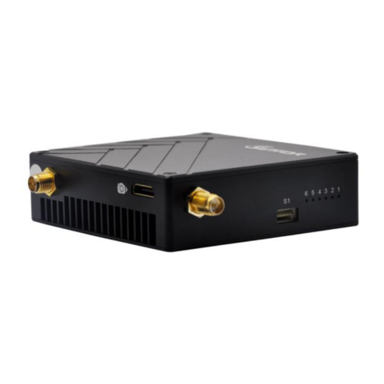
Page 5: Iv.interface Definition
E: Ethernet*1 F: WL indicator*1 G: Screw hollows *4 (for installation) H: SMA antenna *1 (AUX Antenna) I: S1 TTL serial port*1 J: Working station indicators * 6 K: SMA antenna *1 (Main Antenna) L: HDMI mini*1(No available for ST20NPT) -
Page 6: Rx Interface Definition
4.2. RX Interface Definition 4.2.1. RF Interface RF: Standard SMA to connect with antenna or feeder cable 4.2.2. Ethernet Port ETH:EZH 4P 1.5mm ETH Signal Definition 4.2.3. Power Input Interface DC: 3.5×1.35(Male) to 5.5×2.1(Female) -
Page 7: Operating Instructions & Steps
4.2.4. Serial Port: : H 1.0mm 5P SH 5P NO. Definition 3.3V No Definition V. Operating Instructions & Steps 5.1. Make TX and RX and accessories ready. Besides the whole equipment we supply, you also need to make sure the IP Camera, display and power ready before operating. -
Page 8: Connection
5.2. Connection Make the power cable, Ethernet cable, serial port cable and antennas in good connection. (the serial port cable is for data links) 5.3. Power on After checking all the connections are in good condition, turn on the the IP Camera, PC, transmitter and receiver. The indicators will bright and the whole system starts work. -
Page 9: Definition Of Indicators
5.4. Definition of indicators 5.4.1. TX Indicators Definition After powering on, the devices will boot normally. Then the indicators’ normal state will be as follows: (1) Indicator light 1, 2, 3 and 6 will turn on in green color. (2) After one second, indicator light 1(green), 2(green), 3(green) and 6(blue) will start to blink. -
Page 10: Antenna Installation
VI. Antenna Installation 6.1. Multi-rotor UAV SMA Feeder Cable 1) Using SMA metal shielded semi-flexible blue feeder cable provided by SUNTOR to connect the TX SMA port with antenna. 2) The antenna needs to be mounted vertically downwards. 3) The best installation location is UAV ground bracket. -
Page 11: Fixed Wing Uav
7.1. Two ways for changing the parameters The parameters can be changed by software SUNTOR supplied such as bandwidth, code stream and so on. Two windows for device on board and ground station can be operated at the same time to do monitoring or setting. The... -
Page 12: How To Use The Software
SNR (db) / RSSI (dbm) will be updated in real time. Notes:As for one pair of our devices, their parameters should be consistent, which means when you change one of them, you have to change another one, or they will lose connection. There are two ways to modify the parameters. -
Page 13: Rf Configuration
Next click Connect TDD button. 7.2.2. RF Configuration Take TX as a sample, In RF Part, you can modify six parameters listed in the following picture: TX Rate, TX Power, Channel Bandwidth, Channel Frequency, Wireless Distance, TX-RX as the follow pic. TX Rate (Default: QPSK FEC 1/2) This setting determines the modulation type and rate that the data will be wirelessly transferred. - Page 14 Channel-Frequency (Default: 2479Mhz) 2402 - 2482 (1MHz BW, CH 1-81) 2402 - 2482 (2MHz BW, CH 1-81) 2405 - 2479 (4MHz BW, CH 4-78) 2407 - 2477 (8MHz BW, CH 6-76) Wireless Distance (Default: e.g.,ST11HPT 10km) The Wireless Distance parameter allows a user to set the expected distance that the wireless signal needs to travel.
-
Page 15: Rs1 Configuration
TX Power(Default: 29dbm) This setting establishes the transmit power level which will be presented to the antenna connector of the TDD_COFDM. Unless required, the Tx Power should not be set into maximum, but rather for the minimum value required to maintain an adequate system fade margin. -
Page 16: Rs2 Configuration
Data Format (Default: 8N1) This setting determines the format of the data on the serial port.The default is 8 data bits, No parity, and 1 Stop bit. 7.2.4. RS2 Configuration This setting determines which protocol the serial server will use to transmit serial port data over the TDD-COFDM network. -
Page 17: Ip New Network Configuration
7.2.5. IP New Network Configuration This setting helps you to change the IP address of devices. The default of master’s IP address is 192.168.55.1. The default of slave’s IP address is 192.168.55.2 For example, if you want to change the master’s IP address to “192.168.55”.
Need help?
Do you have a question about the ST20NPT and is the answer not in the manual?
Questions and answers