
Related Manuals for Acdeos AXS FL


Summary of Contents for Acdeos AXS FL
- Page 1 AXS – Ramp Manual AXS – FL Ramp Manual Acdeos BV Touwbaan 1A 2352 CZ Leiderdorp Netherlands www.ACDEOS.com Date: 3-4-2020 Doc AR9000 04 Rev. 2...
-
Page 2: Table Of Contents
Maximum load 400 Kg (4000 N) This is always labeled on the Ramp. Materials Ramp; Anodized Aluminium structure with Aluminium profile anti-slip platform. Integrated Aluminium hinge. Mounting points: steel. Legislation The product complies with the 2006/42/EC and NEN-EN 1756-1 AXS FL RAMP Manual rev 1... -
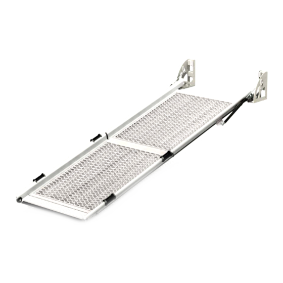
Page 3: Nomenclature
Meaning a AR FL 210-8/2 is a AXS ramp of the FL series with a 2,1 meter length, 0,86 meter width in two parts (platforms). Components of the double ramps 1. first platform 2. second platform 3. feet assembly 4. fixation kit AXS FL RAMP Manual rev 1... -
Page 4: Safety Instructions
13. In case of exchanged parts – only the original parts of the ramp must be used. 14. Always use the recommended cleaning materials. 15. Report any unsafe conditions of the ramp or problems during operation to the ramp supplier. AXS FL RAMP Manual rev 1... -
Page 5: Constraints
Notes 1) measured from a curbstone of 150 mm ACDEOS recommends a maximum slope of 25 % when the wheelchair passenger has assistance from trained staff. If the person has to enter the vehicle by himself the maximum slope should be 12 %. -
Page 6: Operation
It will go out and open automatically. Do NOT use the emergency operation as the standard way to open the ramp, this will cause damage to the ramp! AXS FL RAMP Manual rev 1... -
Page 7: Mounting / Installation
No modification of the chassis is needed. Exact measurements of the product should be taken from official installation drawings. Ask Acdeos for the final revision and official installation drawing. The figures and drawings used in this manual are for indication only. - Page 8 These bolts can be purchased from a local supplier. Bolts used must be to DIN 912 / ISO 4762 specification M10 x length (as regulated) – 10.8. AXS FL RAMP Manual rev 1...
-
Page 9: Place Brackets Left And Right
Position the bracket so that the rubber aligns with the rail of the ramp. Place brackets left and right Adjust the brackets so the ramp is held tight when the door is closed. AXS FL RAMP Manual rev 1... -
Page 10: The Black Nylon Roll Is Eccentrically And Can Be Adjusted If The Ramp Lock Is To Loose
If this small test procedure is followed with success the ramp is ready to be used. If one of the steps is failed please resolve the problem before putting the ramp in to service use. AXS FL RAMP Manual rev 1... - Page 11 - Make sure it is mounted as far to the plastic end cap as possible. - Tighten the bolts M8 (30 Nm) - check the position of the T nuts AXS FL RAMP Manual rev 1...
- Page 12 At a flat ground, with the ramp unfolded from the vehicle, the legs should be approx. 1 cm free from the floor. Fix the legs with the set screw. 1 cm free And you are ready AXS FL RAMP Manual rev 1...
- Page 13 Needed tools: size 13 wrench, allen key size 5 Remove the m8 nut from the gas spring. Do not remove the gas spring from the hole. Place the bump stop assembly on the feet. Open the ramp AXS FL RAMP Manual rev 1...
- Page 14 Close the ramp and adjust the bracket so the rubber bump stops aligns with counterpart Check the t-nuts for being fit properly square on the slot Tighten all nuts and bolts to 30 Nm 30 Nm Repeat on other side AXS FL RAMP Manual rev 1...
- Page 15 Mark out the position for the 4x M10 mounting bolts for the Mounting plates. Drill the 4 (Ø10.5mm) holes through the floor in a rectangular pattern of 956mm x 155 mm this is a different pattern as for fixed installation AXS FL RAMP Manual rev 1...
- Page 16 Place the distance bar between the two feet assemblies Fit the toggle device at the left and right feet. Carle full there is a left and right device. Fix with the two M8 screws together with the distance bar. AXS FL RAMP Manual rev 1...
- Page 17 Position the bracket so that the rubber aligns with the rail of the ramp. Place brackets left and right Adjust the brackets so the ramp is held tight when the door is closed. AXS FL RAMP Manual rev 1...
- Page 18 If this small test procedure is followed with success the ramp is ready to be used. If one of the steps is failed please resolve the problem before putting the ramp in to service use. AXS FL RAMP Manual rev 1...
- Page 19 You can choose the direction of the locking lever pointing side or rear Use blue Loctite on the M6 wire from the center piece to prevent it from loosening Same for Left or right version AXS FL RAMP Manual rev 1...
- Page 20 Locate the exact position where the ramp will be fitted at the floor. The ramp should be placed as close as possible to the door, leaving 3-7cm clearance space when the door is closed. AXS FL RAMP Manual rev 1...
- Page 21 4 x M10 countersunk bolts. Once fitted to the turning plate, remove the steel and wooden distance piece between the feet assemblies Left or right version mirrored AXS FL RAMP Manual rev 1...
- Page 22 Use the U shape counter brackets under the vehicle. Fix the top bracket to the wall with the two M8 bolts at the rivet nuts that already have been put in place. Fix all bolts firmly Left or right version mirrored AXS FL RAMP Manual rev 1...
- Page 23 Position the bracket so that the rubber aligns with the rail of the ramp. Place brackets left and right Adjust the brackets so the ramp is held tight when the door is closed. AXS FL RAMP Manual rev 1...
- Page 24 If this small test procedure is followed with success the ramp is ready to be used. If one of the steps is failed please resolve the problem before putting the ramp in to service use. AXS FL RAMP Manual rev 1...
-
Page 25: Maintenance
The inspection of the ramp can only be done by a company that is familiar with ramps and lifting devices and which has trained staff. This is a people caring device. ACDEOS recommends inspection maintenance should be carried out yearly. -
Page 26: Repair
When there are no signs of wear separate the lower ball joint in a similar way as described above AXS FL RAMP Manual rev 1... - Page 27 Slide the bracket as far as possible up and tighten the M8 bolts firmly again using a 5mm Allan key. Unfold the ramp Remove the pre-tension rings, close the ramp and you are ready. AXS FL RAMP Manual rev 1...
- Page 28 Unfold the ramp, remove the middle gas spring from the ramp and take off the brackets. Fix the gas springs to the brackets or mounting plates before installing on the ramp. AXS FL RAMP Manual rev 1...
- Page 29 For the models of the 250 series, the bracket should be placed as shown left. The drawing on the right shows the situation for an heavy duty ramp and gas spring. AXS FL RAMP Manual rev 1...
-
Page 30: Adjustment Of The Auto Lock
Take out the large bolt, add or remove conical rings and tighten the bolt again, make sure there are equal amounts of conical rings on each of the bolts. (conical rings part number is AR 380) AXS FL RAMP Manual rev 1... -
Page 31: Spare Parts
AR 060 Alu end cap (Bolt side) AR 077 End flap with Logot AR 243 Conical ring AR 380 End Alu cap AR 053 Alu end cap AR 053 Wheel kit (new) AR 200 079 AXS FL RAMP Manual rev 1... - Page 32 AR 200 005 / 004 + AR 032 / 116 Lock mechanism right AR 200 006 / 004 + AR 032 /116 Lower Gas Spring AR 200 060 Mounting kit 1x AR 200 023 Bump stop AR 047 Bracket gas spring AR 360 AXS FL RAMP Manual rev 1...
-
Page 33: Additional Kits
AR 270 Bump stop kit AR 200 096 11 Environment The AXS ramp is made of durable materials which can all be recycled. Each different material can be easily being separated for individual recycling. AXS FL RAMP Manual rev 1... -
Page 34: Ce Certification
The loading recommendations in the Machine directive 2006/42/EC and NEN-EN 1756-1 Ramp is tested for a maximum weight of 400 Kg On behalf of producer: Name / Function A de Moes / Engineering Date 12 December 2012 Place Leiderdorp, Netherlands AXS FL RAMP Manual rev 1... -
Page 35: M1 Certification
The ramp construction is strong enough resist a 20G force corresponding 76/115 EC in standing (closed) position On behalf of producer: Name / Function A de Moes / Engineering Date 22 February 2013 Place Leiderdorp, Netherlands AXS FL RAMP Manual rev 1... - Page 36 AXS – Ramp Manual AXS FL RAMP Manual rev 1...
-
Page 37: Appendix I; Installation Drawing Double Ramps
AXS – Ramp Manual Appendix I; Installation drawing Double ramps: Dimensions in mm Type AR FL 210-8 / 2 2120 1150 AR FL 250-8 / 2 2520 1350 AR FL 280-8 / 2 2820 1500 AR FL 280-10 / 2 2820 1500... -
Page 38: Appendix Ii: Drill Tool
AXS – Ramp Manual Appendix II: Drill tool 4 Holes at 1004 x 210 for fixed mounting of the ramp 4 Holes at 956 x 155 for mounting with optional quick out kit AXS FL RAMP Manual rev 1...
Need help?
Do you have a question about the AXS FL and is the answer not in the manual?
Questions and answers