Table of Contents
Advertisement
Quick Links
Advertisement
Table of Contents

Related Manuals for EDI SmartMonitor MMU-16LE Series


Summary of Contents for EDI SmartMonitor MMU-16LE Series
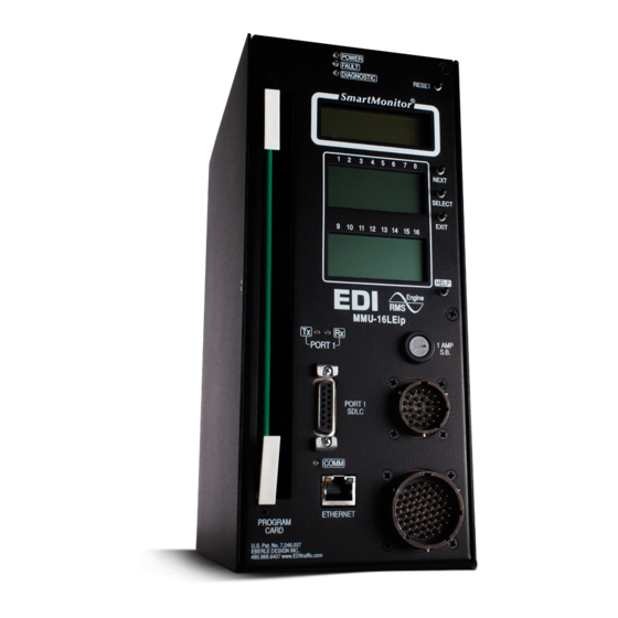
- Page 1 MMU-16LE Series ® SmartMonitor NEMA TS-2 Enhanced Malfunction Management Unit Operations Manual THIS MANUAL CONTAINS TECHNICAL INFORMATION FOR THE MMU-16LE and ® MMU16LEip SmartMonitor SERIES MALFUNCTION MANAGEMENT UNIT. REVISION: APRIL 2012 pn 888-0116-001...
- Page 2 INFORMATION CONTAINED HEREIN IS PROPRIETARY TECHNICAL INFORMATION OF EBERLE DESIGN INC. PUBLICATION, REPRODUCTION OR USE IN WHOLE OR PART IS NOT PERMITTED EXCEPT UNDER TERMS AGREED UPON IN WRITING. © COPYRIGHT 2004-2012 EDI Canadian Patent No. 2,574,101 U.S. Pat. No. 7,246,037 MAINTENANCE NOTE THIS EBERLE DESIGN INC.
-
Page 3: Table Of Contents
Table of Contents Section 1 General........................1 1.1 Description........................1 1.2 Advanced Feature Overview ..................1 1.2.1 Liquid Crystal Status and Field Display ............. 1 1.2.2 Menu Driven Operation ..................1 1.2.3 Context Sensitive Help System ................. 1 1.2.3.1 Set-up Wizard ................... 1 1.2.3.2 Diagnostic Wizard .................. - Page 4 3.12.1 Basic PPLT5 Arrow Suppression Mode ............22 3.12.2 PPLT5 Arrow Suppression Channel Assignment Diagrams......24 Section 4 ECcom Interface ....................25 4.1 EDI ECcom Monitor Reports ..................25 4.1.1 General Data ....................25 4.1.2 Current Status (S) .................... 25 4.1.3 Previous Fault (PF) Event Log .................
- Page 5 6.3.4.4 External Watchdog Enable Option ............33 6.3.4.5 +24V-II = 12 Vdc Enable Option ............33 6.3.4.6 Program Card Memory Enable Option ..........33 ® 6.3.4.7 LEDguard Enable Option ..............33 6.3.4.8 Force Type 16 Mode Enable Option ............33 6.3.4.9 Type 12 With SDLC Mode Enable Option ..........
- Page 6 10.3.2 Type 12 Connector MS-B Pin Terminations ..........46 10.4 MMU16LE-RM & MMU16LEip-RM Rack Mount Connector ........46 10.5 Programming Card Pin Connections ............... 47 10.5.1 Programming Card P1 Connector ..............47 10.5.2 Programming Card P2 Connector ..............48 10.6 Port 1 Connector ...................... 49 10.7 EIA-232 Connector ....................
-
Page 7: Section 1 General
MMU-16LE SmartMonitor Operations Manual Section 1 General 1.1 DESCRIPTION ® The MMU-16LE SmartMonitor series Malfunction Management Unit (MMU) is a device used in a Traffic Controller Assembly to accomplish the detection of, and response to, improper and conflicting signals and improper operating voltages in a Controller Assembly caused by malfunctions of the Controller Unit (CU), load switches, or mis-wiring of the ®... -
Page 8: Program Card Memory
The MMU-16LE SmartMonitor stores these signal records for the last five fault events. The EDI ECcom software (Version 3.5.8 or greater is required) is available at no charge from the EDI web site at www.EDItraffic.com. 1.2.7 NEMA TS-1 OPERATION WITH SDLC MODE ®... -
Page 9: Five Section Arrow Suppression Protected-Permissive Movement (Pplt5)
MMU-16LE SmartMonitor Operations Manual 1.2.9 FIVE SECTION ARROW SUPPRESSION PROTECTED-PERMISSIVE MOVEMENT (PPLT5) ® The MMU-16LE SmartMonitor is designed to monitor an intersection with up to four approaches using the five section PPLT5 Arrow Suppression movement. The MMU-16LE ® SmartMonitor has been designed to provide the same broad fault coverage for the PPLT5 Arrow Suppression approaches as it does for conventional protected left turn phases including Conflict, Red Fail, Dual Indication, and both Minimum Yellow and Minimum Yellow Plus Red Clearance monitoring. -
Page 10: Field Signal Terminals
MMU-16LE SmartMonitor Operations Manual make enhanced event logging, remote intersection monitoring, and remote diagnostics ® feasible. Similarly, the MMU-16LE SmartMonitor receives information from the Controller Unit which corresponds to the Controller Unit output commands to the load switches. This ® allows the MMU-16LE SmartMonitor to better respond to and diagnose fault situations. -
Page 11: Type 12 With Sdlc Mode
MMU-16LE SmartMonitor Operations Manual Traffic Control Systems Publication TS1-1989. When operating in the Type 12 mode, the ® MMU-16LE SmartMonitor monitoring functions are the same as the Type 16 mode except that Port 1 communications are disabled and Field Check Monitoring is disabled. See also TYPE 12 MODE WITH SDLC Option, section 1.4.2.1. -
Page 12: Force Type 16 Mode
MMU-16LE SmartMonitor Operations Manual 1.4.2.2 FORCE TYPE 16 MODE If the cabinet is already wired for 16 channel operation but the TYPE SELECT input is not ® accessible due to cabinet wiring issues, the MMU-16LE SmartMonitor can be forced to the Type 16 mode by setting the FORCE TYPE 16 option in Unit Options. -
Page 13: Section 2 Standard Functions
MMU-16LE SmartMonitor Operations Manual Section 2 Standard Functions 2.1 CONFLICT MONITORING When voltages on any conflicting channels are sensed as active for more than the Conflict ® Fault time (Section 9), the MMU-16LE SmartMonitor will enter the fault mode, transfer the OUTPUT relay contacts to the Fault position, and display the CONFLICT status screen. -
Page 14: Voltage Monitoring
MMU-16LE SmartMonitor Operations Manual 2.3 VOLTAGE MONITORING 2.3.1 +24VDC SUPPLY MONITORING The +24V MONITOR I and +24V MONITOR II inputs are provided for monitoring two +24Vdc supplies in the cabinet assembly. Should loss of proper voltage occur at either of ®... -
Page 15: Cvm Monitor Latch Input
MMU-16LE SmartMonitor Operations Manual 2.3.2.1 CVM MONITOR LATCH INPUT A jumper position is supplied on the Programming Card to allow CVM failures to latch in the fault condition until the unit is reset by the activation of the RESET button or the EXTERNAL RESET input. -
Page 16: Minimum Yellow Plus Red Clearance Disable
MMU-16LE SmartMonitor Operations Manual 2.5.2.1 MINIMUM YELLOW PLUS RED CLEARANCE DISABLE The Red + Yellow Clearance Disable Configuration screen is provided in the SET / VIEW CONFIG menu to disable Minimum Yellow Plus Red Change Monitoring on a per channel basis. -
Page 17: Port 1 Timeout
MMU-16LE SmartMonitor Operations Manual (Type 129), channel compatibility programming (Type 131). The load switch driver command (Type 0) and field signal status (Type 129) messages are exchanged approximately every 100 msec. The electrical interface used for Port 1 conforms to the requirements of the Electronic Industries Association EIA-485 Standard. -
Page 18: Output Relay Recovery
MMU-16LE SmartMonitor Operations Manual 2.9 OUTPUT RELAY RECOVERY ® Prior to the MMU-16LE SmartMonitor transferring the Output Relay contacts from the fault state to the no-fault state, a transition state with duration of 500 milliseconds will occur. During the transition state the Output Relay will remain in the fault state and the Start-up Flash Call bit in the Type 129 frame will be set to 1. -
Page 19: Section 3 Enhanced Features
MMU-16LE SmartMonitor Operations Manual Section 3 Enhanced Features The following enhanced features are provided on the Eberle Design MMU-16LE ® SmartMonitor for additional monitoring functions and to increase the reliability of the MMU- ® 16LE SmartMonitor monitor operation. 3.1 HARDWARE FEATURES ®... -
Page 20: Walk Disable Option
MMU-16LE SmartMonitor Operations Manual Programming for Dual Indication is provided in the SET / VIEW CONFIG menu item to enable Dual Indication Monitoring on a per channel basis. See Section 6.3.2 for the programming procedure. Dual Indication Monitoring will be disabled when the RED ENABLE input is not active. 3.2.1 WALK DISABLE OPTION This option will modify the operation of Red Fail and Dual Indication Monitoring in the TS-1 Type 12 mode only. -
Page 21: Recurrent Pulse Detection
MMU-16LE SmartMonitor Operations Manual 3.7 RECURRENT PULSE DETECTION This error detection function supplements the normal Conflict, Dual Indication, and Red Fail monitoring algorithms for sensing faults which are intermittent or pulsing in nature. The ® RMS-Engine is designed to filter out short term transients commonly found on the electrical service and provide noise immunity against false signal detections. -
Page 22: Field Check Monitoring
MMU-16LE SmartMonitor Operations Manual 3.9 FIELD CHECK MONITORING ® Field Check Monitoring is an enhanced function of the MMU-16LE SmartMonitor that utilizes the Port 1 communications between the Controller Unit and the MMU in a TS2 ® Cabinet Assembly. When operating in the Type 16 mode the MMU-16LE SmartMonitor will receive the Type 0 message from the Controller Unit (Type 1 or Type 2 CU) which contains an image of the controller output commands to the load switches. -
Page 23: Diagnostic Wizard
MMU-16LE SmartMonitor Operations Manual 3.10 DIAGNOSTIC WIZARD The built-in Diagnostic Wizard is an integral part of the Help System that provides detailed diagnostic information regarding the fault being analyzed. The Wizard provides a concise view of the signals involved in the fault, pinpoints faulty signal inputs, and provides guidance on isolating the cause of the malfunction. -
Page 24: Flashing Yellow Arrow Protected-Permissive Monitoring (Fya)
(permissive), and solid Green Arrow (protected). - NOTE - EDI does not provide any guidelines, warrants, or recommendations for the use of protected/permissive left-turn phasing. The underlying assumption is that the traffic engineer has decided that this form of protected/permissive control is the most appropriate left-turn treatment, and all necessary considerations have been made. -
Page 25: Compact Fyac Mode
MMU-16LE SmartMonitor Operations Manual Channel conflicts are detected based on the Permissive programming jumpers on the Program Card for each channel. This operation remains unchanged from normal Nema operation. Red Fail A Red Fail fault will occur if the solid Red Arrow AND solid Yellow Arrow AND flashing Yellow Arrow AND solid Green Arrow all remain inactive for the Red Fail fault response time. -
Page 26: Fyac Type 12 Mode
MMU-16LE SmartMonitor Operations Manual the Controller Unit be capable of remapping the Protected Green Arrow signal driver to the channel 9, 10, 11, and 12 Yellow load switch inputs. ® If a channel pair is enabled for FYAc operation, the MMU-16LE SmartMonitor will monitor the FYA logical channel pair for the following fault conditions: Conflict... -
Page 27: Fya Channel Assignment Diagrams
MMU-16LE SmartMonitor Operations Manual ® If a channel pair is enabled for FYAc operation, the MMU-16LE SmartMonitor will monitor the FYA logical channel pair for the following fault conditions: Conflict i. Channel conflicts are detected based on the Permissive programming jumpers on the Program Card for each channel. -
Page 28: Five Section Arrow Suppression Protected-Permissive Monitoring (Pplt5)
RYG Ball section is intended for the thru vehicle phase. - NOTE - EDI does not provide any guidelines, warrants, or recommendations for the use of protected/permissive left-turn phasing. The underlying assumption is that the traffic engineer has decided that this form of protected/permissive control is the most appropriate left-turn treatment, and all necessary considerations have been made. - Page 29 MMU-16LE SmartMonitor Operations Manual ® MMU-16LE SmartMonitor associates channel 1 with 13 [9], channel 3 with 14 [10], channel 5 with 15 [11], and channel 7 with 16 [12] when PPLT5 Arrow Suppression monitoring is enabled for that respective approach. If a channel pair is enabled for PPLT5 Arrow Suppression operation, the MMU-16LE ®...
-
Page 30: Pplt5 Arrow Suppression Channel Assignment Diagrams
MMU-16LE SmartMonitor Operations Manual 3.12.2 PPLT5 ARROW SUPPRESSION CHANNEL ASSIGNMENT DIAGRAMS Type 16 Mode Type 12 Mode Green and Yellow Ball Red, Yellow, Green Arrow Pedestrian Eberle Design Inc. Page 24... -
Page 31: Section 4 Eccom Interface
Operation of the ECcom software package is described in EDI ECcom Software Operations Manual and will not be covered in this manual. The EDI ECcom software is available at no charge from the EDI web site at www.EDItraffic.com. -
Page 32: Manual Reset (Mr) Event Log
IP address and Subnet Mask. The network port parameters are set or changed using the ® ® EDI ECcom Signal Monitor Communications software. See the "EDI ECcom Software Operations Manual" ETHERNET LAN SETTINGS Section 3.2.1.2 for details. Eberle Design Inc. -
Page 33: Section 5 Menu Operation
MMU-16LE SmartMonitor Operations Manual Section 5 Menu Operation 5.1 MAIN STATUS MENU The menu driven user interface follows the map shown below. At the top level, the NEXT button selects whether Current Status details or the main Menu selections are displayed. The NEXT button is used to scroll through the various selections that each menu level may provide. -
Page 34: Menu
MMU-16LE SmartMonitor Operations Manual 5.2.2 MENU Pressing the NEXT button followed by the SELECT button from the top level provides the main Menu structure for selecting the following functions: 5.2.2.1 VIEW LOGS This menu category provides a review of: Previous Failure (PF) log AC Line (AC) event log Monitor Reset (MR) log Events are stored with #1 being the newest event in the log. -
Page 35: Clear Logs
Port 1 SDLC communications. The day and date clock will automatically adjust for Daylight Savings time. The week and month that this occurs can be programmed via the ECcom interface (see EDI ECcom Software Operations Manual). Eberle Design Inc. -
Page 36: Section 6 Installation
The EDI ECcom software can also be used to develop the configuration parameters. This is the same process as using the front panel menu driven interface but is easier due to the personal computer interface. -
Page 37: Minimum Flash Time Programming
MMU-16LE SmartMonitor Operations Manual 6.2.2 MINIMUM FLASH TIME PROGRAMMING ® The MMU-16LE SmartMonitor Programming Card contains a group of soldered wire jumper holes to set the Minimum Flashing Indication time after an MMU Power Failure. The programming of the Minimum Flash time is in a binary encoded format. The addition of a soldered wire jumper in a jumper hole pair will add that designated input value to the binary weighted sum plus 1 second (minimum period is 6 seconds). -
Page 38: Enhanced Function Programming
Alternatively, the data can be designed or downloaded from disk file using the ECcom software. All Enhanced Function programming values are simultaneously stored in the non-volatile memory on the EDI Program Card (see Section 6.3.4.6). -
Page 39: Unit Option Programming
12Vdc to the ON state. See Section 2.3.1.3. The Factory Default setting is OFF. 6.3.4.6 PROGRAM CARD MEMORY ENABLE OPTION The nonvolatile memory interface on the EDI Program Card is ENABLED by setting PGM CARD MEMORY to the ON state. See Section 1.2.4. The Factory Default setting is OFF. -
Page 40: View Program Card Options
Menu Path: MENU / SET VIEW CONFIG / MONITOR ID, NAME The monitor ID number and text name can be displayed. These settings are read-only and are set or changed using the EDI ECcom software. 6.3.9 VIEW FIRMWARE VERSION Menu Path: MENU / SET VIEW CONFIG / FIRMWARE VERSION The monitor firmware version can be displayed. -
Page 41: Set Atsi Default Programming
MMU-16LE SmartMonitor Operations Manual Function Factory Default Log CVM Faults Enabled External Watchdog Disabled 24V-2 = 12Vdc Disabled Program Card Memory Disabled LEDguard Disabled Force Type 16 Disabled Flashing Yellow Arrow Disabled Y+R Clearance Monitor Enabled PPLT5 Suppression Disabled Monitor ID, Name Not Affected 6.3.12 SET ATSI DEFAULT PROGRAMMING Menu Path:... -
Page 42: Set-Up Wizard
MMU-16LE SmartMonitor Operations Manual PPLT5 Arrow Suppression Channel Groups Phase Type 16 Type 12 Red, Yellow, & Green Arrow 1, 3, 5, 7 1, 3, 5, 7 Yellow & Green Ball 13, 14, 15, 16 9, 10, 11, 12 This screen enables each channel pair for PPLT Arrow Suppression monitoring. If a channel pair is not enabled, both associated channels operate in a normal fashion. -
Page 43: Protected-Permissive Turn Channels
MMU-16LE SmartMonitor Operations Manual 6.4.3 PROTECTED-PERMISSIVE TURN CHANNELS ® This step selects the channels of the MMU-16LE SmartMonitor that are connected to a protected-permissive left turn channel load switch that drives only a Green and Yellow signal display. This selection can eliminate the need to connect the Red input of a protected-permissive turn channel to AC+. -
Page 44: Section 7 Front Panel Description
MMU-16LE SmartMonitor Operations Manual Section 7 Front Panel Description 7.1 MAIN STATUS DISPLAY ® The Main Status Display of the MMU-16LE SmartMonitor is used to display the current ® status of the MMU-16LE SmartMonitor and navigate the menu levels. When the monitor is not in the fault mode, the Main Status display will show current monitor status. -
Page 45: Front Panel Buttons
MMU-16LE SmartMonitor Operations Manual 7.4 FRONT PANEL BUTTONS 7.4.1 RESET BUTTON ® Depressing the RESET button resets the MMU-16LE SmartMonitor after it has been triggered by a fault. When the RESET button is depressed all front panel indicators will be illuminated for 500 msec and the OUTPUT relay and START DELAY relay energized. -
Page 46: Section 8 Specifications
MMU-16LE SmartMonitor Operations Manual Section 8 Specifications 8.1 ELECTRICAL 8.1.1 POWER REQUIREMENTS Operating Line Voltage ................75 to 135 Vrms Operating Line Frequency ..................60 + _ Power Consumption ................... 10W (nominal) 8.1.2 AC VOLTAGE MONITORS Nema Green Signal Inputs No Detect ..................less than 15 Vrms Detect.................. -
Page 47: Environmental
MMU-16LE SmartMonitor Operations Manual 8.3 ENVIRONMENTAL Storage Temperature Range ..............-45 to +85 Operating Temperature Range ..............-34 to +74 Main Status LCD Operating Temperature Range ........-20 to +74 Channel Status LCD Operating Temperature Range ........ -34 to +74 Humidity Range (non-condensing) ............ -
Page 48: Section 9 Timing Functions
MMU-16LE SmartMonitor Operations Manual Section 9 Timing Functions Conflict No Fault ..................less than 200 msec Fault ..................greater than 450 msec Typical ......................350 msec Red Fail No Fault ..................less than 700 msec Fault ..................greater than 1000 msec Typical ...................... -
Page 49: Section 10 Wiring Assignments
MMU-16LE SmartMonitor Operations Manual Section 10 Wiring Assignments 10.1 HARNESSING CONNECTORS ® All field signal terminations are brought into the MMU-16LE SmartMonitor by means of Military Specification MIL-C-26482 connectors. These connectors are interchangeable with 12 channel monitors as defined by NEMA Traffic Control Systems Specification TS1-1989, part 6. -
Page 50: Type 16 Connector Ms-B Pin Terminations
MMU-16LE SmartMonitor Operations Manual Function Channel 3 Yellow Channel 15 Green Channel 2 Yellow Channel 1 Yellow Controller Voltage Monitor +24V Monitor Inhibit Output Relay 1 Closed (Stop Time) (Opens when fault occurs) Output Relay 2 Open (FTR Drive) (Closes when fault occurs) Channel 12 Walk (Type 12 only) Channel 11 Walk (Type 12 only) Channel 9 Walk (Type 12 only) -
Page 51: Type 12 Terminations
MMU-16LE SmartMonitor Operations Manual 10.3 TYPE 12 TERMINATIONS 10.3.1 TYPE 12 CONNECTOR MS-A PIN TERMINATIONS Function AC Line Output Relay 1 Open (Stop Time) (Closes when fault occurs) Output Relay 2 Closed (FTR Drive) (Opens when fault occurs) Channel 12 Green Channel 11 Green Channel 10 Green Channel 9 Green... -
Page 52: Type 12 Connector Ms-B Pin Terminations
MMU-16LE SmartMonitor Operations Manual Function Channel 1 Walk Spare 1 Reset Cabinet Interlock A Cabinet Interlock B Channel 6 Walk Channel 4 Walk Spare 2 Type Select 10.3.2 TYPE 12 CONNECTOR MS-B PIN TERMINATIONS Function AC Line Start-Delay Relay Common Start-Delay Relay Open (Closes during Start Delay period) Channel 12 Red... -
Page 53: Programming Card Pin Connections
MMU-16LE SmartMonitor Operations Manual Description Description Description +24 Volt Monitor I PORT1 TxD - PORT1 TxD + +24 Volt Monitor II Reserved Port 1 Disable Channel 1 Green Channel 1 Yellow Channel 1 Red Channel 2 Green Channel 2 Yellow Channel 2 Red Channel 3 Green Channel 3 Yellow... -
Page 54: Programming Card P2 Connector
MMU-16LE SmartMonitor Operations Manual 1-10 1-11 1-12 1-13 1-14 1-15 1-16 2-10 2-11 2-12 2-13 2-14 2-15 2-16 3-10 3-11 3-12 3-13 3-14 3-15 3-16 4-10 4-11 4-12 4-13 4-14 4-15 4-16 5-10 5-11 5-12 5-13 5-14 5-15 5-16 6-10 6-11 6-12 6-13... -
Page 55: Port 1 Connector
MMU-16LE SmartMonitor Operations Manual MYCD-10 MYCD-11 MYCD-12 MYCD-13 MYCD-14 MYCD-15 MYCD-16 Reserved Reserved Reserved Reserved Reserved Reserved Reserved Reserved Reserved Reserved Reserved Reserved Reserved Reserved Reserved Reserved Reserved Minimum Flash b8 Minimum Flash b4 Minimum Flash b2 Minimum Flash b1 24V Latch Enable CVM Latch Enable Reserved... -
Page 56: Eia-232 Cable To A Pc
GND pin 5 10.8 ETHERNET LAN PORT (J2) The optional Ethernet port must be configured with specific network parameters such as an IP address, Mask, and Port. The network port parameters are set or changed using the EDI ® ®...
Need help?
Do you have a question about the SmartMonitor MMU-16LE Series and is the answer not in the manual?
Questions and answers