Table of Contents
Advertisement
Quick Links
CMU(ip)-212
ITS Cabinet Monitor Unit
Operations Manual
THIS MANUAL CONTAINS TECHNICAL INFORMATION FOR
THE CMU-212 AND CMUip-212 SERIES ITS CABINET MONITOR UNIT.
Firmware Version 2.5 (vXX25)
REVISION: JUNE 2019
pn 888-0212-001
- NOTE -
EDI ECCOM SOFTWARE MUST BE UPDATED TO VERSION 4.2 OR HIGHER.
EDI MONITORKEY SOFTWARE MUST BE UPDATED TO VERSION 2.4 OR HIGHER.
EDI SOFTWARE IS AVAILABLE AT WWW.EDITRAFFIC.COM
Advertisement
Table of Contents

Subscribe to Our Youtube Channel
Related Manuals for EDI CMU-212


Summary of Contents for EDI CMU-212
- Page 1 Firmware Version 2.5 (vXX25) REVISION: JUNE 2019 pn 888-0212-001 - NOTE - EDI ECCOM SOFTWARE MUST BE UPDATED TO VERSION 4.2 OR HIGHER. EDI MONITORKEY SOFTWARE MUST BE UPDATED TO VERSION 2.4 OR HIGHER. EDI SOFTWARE IS AVAILABLE AT WWW.EDITRAFFIC.COM...
- Page 2 THE CMU-212 SERIES CABINET MONITOR UNIT IS DESIGNED AND MANUFACTURED IN THE USA BY EBERLE DESIGN INC. PHOENIX, ARIZONA. EDI IS CERTIFIED TO ISO 9001:2015 QUALITY SYSTEMS STANDARDS. INFORMATION CONTAINED HEREIN IS PROPRIETARY TECHNICAL INFORMATION OF EBERLE DESIGN INC. PUBLICATION, REPRODUCTION OR USE IN WHOLE OR PART IS NOT PERMITTED EXCEPT UNDER TERMS AGREED UPON IN WRITING.
-
Page 3: Table Of Contents
2.15.1 Recurrent Pulse Detection Disable .............10 2.16 Flashing Yellow Arrow (FYA) Protected-Permissive Monitoring ......11 2.16.1 FYA Configuration ..................11 2.16.1.1 Protected Turn Channel ..............11 2.16.1.2 Permissive Turn Channel ..............11 2.16.1.3 Opposing Through Channel ..............11 2.16.2 Configuring the CMU-212 Fault Parameters For FYA .........11... - Page 4 2.16.2.1 Conflict .....................12 2.16.2.2 Red Fail ....................12 2.16.2.3 Dual Indication ..................13 2.16.2.4 Minimum Yellow Clearance ...............13 2.16.2.5 Yellow Plus Red Clearance ...............13 2.16.3 Red and Yellow Input Enable ..............13 2.16.4 Flash Rate Detection ..................13 2.16.5 FYA Yellow Trap Conflict Detection............14 Section 3 INPUT SIGNALS ....................15 3.1 Field Signal Inputs ....................15 3.2 Load Switch Current ....................15...
-
Page 5: Section 1 General
Auxiliary Monitor Unit (AMU) located in each Output Assembly via Serial Bus #3. The role of the CMU-212 is to query various cabinet conditions and, if the application requires action, the CMU-212 will transfer control from the Advanced Traffic Controller (ATC) to a flashing control mode. -
Page 6: Cmu-212 Programming
Datakey replaces the mechanical jumper or diode based program card used in conventional signal monitors and provides an electronic method of programming the CMU- 212. The Datakey contains a nonvolatile prom device that is read by the CMU-212. The Datakey itself is programmed by a separate programming device using a Personal Computer program such as the Eberle Design MonitorKey product. -
Page 7: Serial Bus #1
Messages are defined that allow the ATC and the CMU-212 to perform redundant checks on each other. The ATC has access to all CMU-212 information including field signal input status, permissive programming, and fault status. This gives the ATC the capability to provide a backup monitoring function and make enhanced event logging, remote intersection monitoring, and remote diagnostics feasible. -
Page 8: Exit From Fsa
Fault state, a transition period of 500 milliseconds will occur. During the transition period the OUTPUT NO contacts will be in the FSA state and the CMU-212 will set the Start-Up Flash Call bit in the Type 189 Frame to 1. At all other times the Start-Up Flash Call bit of the Type 189 Frame will be set to 0. -
Page 9: Section 2 Monitor Functions
ATC for greater than 1000 milliseconds. The first and second failures in a 24-hour period will be a NFSA. The third failure in a 24-hour period will be a LFSA-R. If a CMU-212 Power Fail resets the LFSA-R, the SB #1 failure count will be reset to two, such that the next SB #1 timeout results in a LFSA-R. -
Page 10: Type 62 Fsa Message
2.4 TYPE 62 FSA MESSAGE If the “N” bit is set in a Type 62 message, the CMU-212 will react by causing a NFSA. The NFSA will remain until the receipt of a Message 62 with the “N” bit cleared or until the CMU-212 is reset by a Unit Reset or CMU-212 Power Fail. -
Page 11: Yellow Plus Red Clearance Monitor
Yellow Change plus Red Clearance interval monitoring on a per channel basis. 2.9 LOCAL FLASH STATUS The CMU-212 will monitor the LF STATUS input. This input is used to indicate to the CMU- 212 that the cabinet should be placed into NFSA as a result of the AUTO/FLASH switch being transferred to the FLASH postion. -
Page 12: Ac+ Raw Level Sense
AMU-214. When any AC+ RAW voltage is less than the AC Line Dropout voltage (section 5.1) for greater than AC Line Level Sense timing (section 5.2) the CMU-212 will cause a NFSA. Once NFSA has been set, the POWERDOWN and NRESET signals will not be monitored until all AC+ RAW voltages have exceeded the AC Line Restore voltage (section 5.1). -
Page 13: Field Check Status
CMU-212 will not cause a LFSA. When a mismatch is detected for 1000 milliseconds or more, the CMU-212 will cause a LFSA. When a mismatch is detected for more than 700 milliseconds but less than 1000 milliseconds, the CMU-212 may or may not cause a LFSA. -
Page 14: Internal Mpu Monitor
FRONT input is sensed as active (door open). 2.14.4 INTERNAL MPU MONITOR The CMU-212 will monitor the operation of its microprocessor with an independent circuit. At a minimum, the monitoring circuit will receive logic state transitions at least once every 50 milliseconds from the microprocessor. -
Page 15: Flashing Yellow Arrow (Fya) Protected-Permissive Monitoring
Operations Manual 2.16 FLASHING YELLOW ARROW (FYA) PROTECTED-PERMISSIVE MONITORING The CMU-212 is designed to monitor an intersection with up to six approaches using the four section Flashing Yellow Arrow (FYA) movement outlined by the NCHRP Research Project 3-54 on Protected/Permissive signal displays with Flashing Yellow Arrows, and complies with all requirements of NEMA Standard TS-2 Amendment 4-2012 Flashing Yellow Arrow. -
Page 16: Conflict
INPUT Enable option is Enabled for that channel. 2.16.2.1 CONFLICT The CMU-212 will verify that no conflicting channels to the solid Yellow arrow channel (clearance) are active as determined by the Program Card compatibility programming of the solid Yellow arrow channel of the pair except during the following sequences: 2.16.2.1.1 PROTECTED YELLOW CHANGE INTERVAL CONFLICT... -
Page 17: Dual Indication
In these cases the Red and Yellow inputs for the sparse FYA channels can be forced to the Off state in the CMU-212 by default. This simplifies the cabinet wiring such that the use of dummy cabinet loads or modifications to the Output harness are not necessary. -
Page 18: Fya Yellow Trap Conflict Detection
When the FYA Yellow Trap Conflict condition is detected, the CMU-212 will enter the fault mode, transfer the OUTPUT relay contacts to the Fault position, and display the “CONFtrap” fault status screen. The CMU-212 will remain in the fault mode until the unit is reset by the RESET button. -
Page 19: Section 3 Input Signals
89 Vrms. This input will not be considered active when the input voltage is less than 70 Vrms. Signals between 89 Vrms and 70 Vrms may or may not be considered active. The CMU-212 will report the state of this input in the Type 189 frame. -
Page 20: Ftr Coil Drive Status
CMU-212 Cabinet Monitor Unit Operations Manual may not be considered active. The CMU-212 will report the state of this input in the Type 189 frame. 3.3.4 FTR COIL DRIVE STATUS The cabinet should be wired such that the FTR COIL DRIVE STATUS input is connected to the FTR COIL DRIVE signal in the AC SIGNAL POWER BUS. -
Page 21: Serial Bus #1 Disable Input
VDC GROUND (True) The CMU-212 will not communicate on Serial Bus #1 or set a FSA condition if communications from the ATC is not present. See section 2.3.1. The SERIAL BUS #1 DISABLE input is intended for use in testing the CMU-212 and should not be connected in the cabinet. -
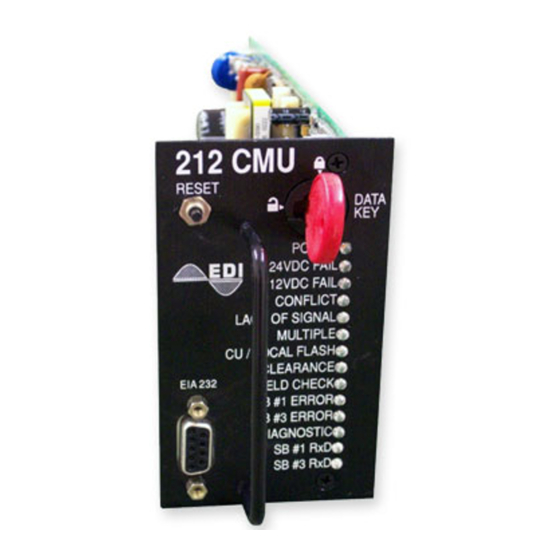
Page 22: Section 4 Front Panel Description
2.12. 4.1.2 24VDC FAIL INDICATOR A red 24VDC FAIL indicator will illuminate when the CMU-212 is in FSA as a result of a 24VDC cabinet power supply fault. The 24VDC FAIL indicator will pulse at a 2 Hz rate when the 24VDC monitor function is disabled. -
Page 23: Sb #1 Error Indicator
4.1.10 SB #1 ERROR INDICATOR A red SB #1 ERROR indicator will illuminate when the CMU-212 is in FSA as a result of a Serial Bus #1 fault. See section 2.3.1. The SB #1 ERROR indicator will pulse at a 2 Hz rate when the SERIAL BUS #1 DISABLE input is True. -
Page 24: Section 5 Specifications
CMU-212 Cabinet Monitor Unit Operations Manual Section 5 SPECIFICATIONS 5.1 ELECTRICAL Power Requirements Operating Line Voltage ................... 75 to 135 Vac Operating Line Frequency ..................60 ± 3 Hz Power Consumption ................10 Watts Maximum AC Voltage Monitors Red Field Signals Active .................. -
Page 25: Mechanical
CMU-212 Cabinet Monitor Unit Operations Manual Fault ..................greater than 1000 ms Serial Bus #3 Error Fault ................... greater than 300 ms Multiple Fault ................... greater than 450 ms No Fault ................... less than 200 ms Typical ......................350 ms Lack of Signal Inputs Fault .................. -
Page 26: Section 6 Connector Assignments
CMU-212 Cabinet Monitor Unit Operations Manual Section 6 CONNECTOR ASSIGNMENTS 6.1 MAIN DIN CONNECTOR CMU-212 main connector 4161264 Header Type: Pin # Function Pin # Function +24VDC Monitor Reserved +12VDC Monitor External Test Reset VDC Ground Serial Bus #1 Disable... -
Page 27: Cmuip-212 Ethernet Lan Port
Reserved 6.3 CMUIP-212 ETHERNET LAN PORT The network port parameters can be set or changed using the EDI ECcom software. The network port parameters can also be configured in the Datakey. See the EDI ECcom Operation Manual (pn 888-1000-001) and MonitorKey Operations Manual (pn 888- 1212-001) for details.
Need help?
Do you have a question about the CMU-212 and is the answer not in the manual?
Questions and answers