Table of Contents
Advertisement
Quick Links
Advertisement
Table of Contents

Related Manuals for EDI DEFLECTOMETER LMD301


Summary of Contents for EDI DEFLECTOMETER LMD301
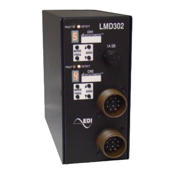
- Page 1 LMD301, LMD302, LMD304 Shelf Mount Series Inductive Loop Monitor Operations Manual THIS MANUAL CONTAINS TECHNICAL INFORMATION FOR THE LMD301, LMD301S, LMD301T, LMD301TS, LMD302, LMD302T, LMD302TS, LMD304, and LMD304S SERIES INDUCTIVE LOOP MONITOR. REVISION: FEBRUARY 2010 pn 888-030X-002...
- Page 2 THE USA BY EBERLE DESIGN INC. PHOENIX, ARIZONA EDI IS CERTIFIED TO ISO 9001:2008 QUALITY SYSTEMS STANDARDS. INFORMATION CONTAINED HEREIN IS PROPRIETARY TECHNICAL INFORMATION OF EBERLE DESIGN INC. PUBLICATION, REPRODUCTION OR USE IN WHOLE OR PART IS NOT PERMITTED EXCEPT UNDER TERMS AGREED UPON IN WRITING.
-
Page 3: Table Of Contents
Table of Contents Section 1 GENERAL ......................1 1.1 Description ......................1 1.2 Overview ........................ 1 1.3 DEFLECTOMETER Feature................... 1 Section 2 Installation and Adjustments ................2 2.1 Set the Sensitivity Level ..................2 ® 2.1.1 Adjusting Sensitivity Using the DEFLECTOMETER (Recommended) .. -
Page 4: Section 1 General
1.2 OVERVIEW A dynamic Overview of the LMD operation which includes an LMD Simulator is available on the EDI Web Site; www.EDItraffic.com. 1.3 DEFLECTOMETER FEATURE The LMD Series Loop Monitor introduces a concept to the inductive loop detector field that revolutionizes the process of installing and programming a loop detector. -
Page 5: Section 2 Installation And Adjustments
LMD301, LMD302, and LMD304 Series Operations Manual Section 2 Installation and Adjustments 2.1 SET THE SENSITIVITY LEVEL ® The DEFLECTOMETER (front panel 7-segment LED display) aids in setting the detector to the most optimum sensitivity level to ensure the detection of all vehicles, including motorcycles and high bed vehicles. -
Page 6: Adjusting Sensitivity Directly
LMD301, LMD302, and LMD304 Series Operations Manual 2.1.2 ADJUSTING SENSITIVITY DIRECTLY The LMD Series offers nine levels of sensitivity (1 to 9). The Sensitivity Level can be manually set to any desired level by pressing the SENS or SENS front panel buttons when a vehicle is NOT over the roadway loop. -
Page 7: Pulse Mode (P)
LMD301, LMD302, and LMD304 Series Operations Manual 2.2.4 PULSE MODE (P) The Pulse mode will provide a 125 ms ± 25ms width output pulse for each vehicle entering the loop.. 2.2.5 CALL MODE (C) The Call mode will set the channel output to the Call state (True). This mode can be used to provide a continuous Call state to the Controller Unit regardless of the state of the detection zone. -
Page 8: Extend Timing
LMD301, LMD302, and LMD304 Series Operations Manual time starts counting down when a vehicle enters the loop detection area. During the Delay ® time the DET indicator will flash two times per second and the DEFLECTOMETER will display the letter “d”. Delay time can be overridden by a True signal at the Timer Control input. -
Page 9: Previous Fault
LMD301, LMD302, and LMD304 Series Operations Manual Flash Sequence Fault 1 flash Open Circuit Loop (or Inductance too high) 2 flashes Shorted Circuit Loop (or inductance too low) 3 flashes >25% Change in Inductance 2.6.2 PREVIOUS FAULT If the fault condition is removed, the DET indicator and the channel output will return to normal operation. -
Page 10: Section 3 Loop Installation
LMD301, LMD302, and LMD304 Series Operations Manual Section 3 Loop Installation The typical sensing height is 2/3 of the shortest leg of a loop (in feet). Therefore a 4’ x 8’ loop typically has a detection height of 2.6’. The inductance of a conventional four-sided loop can be estimated using the formula: L = P x (T + T) / 4 Where L = Loop Inductance in microHenries... - Page 11 LMD301, LMD302, and LMD304 Series Operations Manual circumference to prevent the loop wire from rising up while the sealant is poured and curing. Many different types of loop sealant are now available. Single part types are the easiest to apply since no mixing is required, but they also tend to be more expensive in terms of linear feet of saw slot filled.
-
Page 12: Section 4 Specifications
LMD301, LMD302, and LMD304 Series Operations Manual Section 4 Specifications 4.1 MECHANICAL 4.1.1 LMD301 Height ......................5.5 inches Width ......................2.0 inches Depth (chassis only) ..................5.4 inches 4.1.2 LMD302 AND LMD304 Height ......................6.4 inches Width ......................3.0 inches Depth (chassis only) .................. -
Page 13: Loop Input (Lightning Protection)
LMD301, LMD302, and LMD304 Series Operations Manual 4.5 LOOP INPUT (LIGHTNING PROTECTION) The loop input incorporates lightning and transient protection devices and the loop oscillator circuitry is transformer-isolated for each channel. The lightning protection will withstand the discharge of a 10uF capacitor charged to 2,000V across the loop inputs or between a loop input and Earth Ground. -
Page 14: Lmd304 Connector Pin Assignments
LMD301, LMD302, and LMD304 Series Operations Manual Channel 1 Function Channel 2 Function Ch 1 Output Relay N.O. (Collector) Ch 2 Output Relay N.O. (Collector) Ch 1 Output Relay N.C. Ch 2 Output Relay N.C. Earth Ground Earth Ground No Connect No Connect Ch 1 Timer Control (LMD302T) Ch 2 Timer Control (LMD302T)
Need help?
Do you have a question about the DEFLECTOMETER LMD301 and is the answer not in the manual?
Questions and answers