Table of Contents

Advertisement

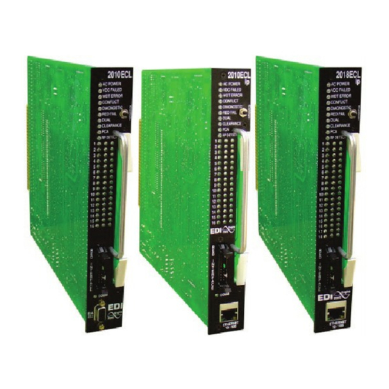
210E - 210ECL - 2010ECL - 2018ECL
RMS Signal Monitor
Operations Manual
THIS MANUAL CONTAINS TECHNICAL INFORMATION FOR THE FOLLOWING SERIES
OF MODEL 210/2010/2018 SIGNAL MONITORS, PCB Issue G:
210E, 210ECL, 2010, 2010ECL, 2010ECLip, 2018ECL, 2018ECLip
- NOTE -
EDI ECCOM SOFTWARE MUST BE UPDATED TO VERSION 3.8.0 OR
GREATER FOR COMPATIBILITY WITH THIS FIRMWARE VERSION.
THE ECCOM SOFTWARE IS AVAILABLE FREE OF CHARGE AT
WWW.EDITRAFFIC.COM
REVISION: NOVEMBER 2014
pn 888-2010-002

Advertisement

Table of Contents
loading

Summary of Contents for EDI 210E

  • Page 1 OF MODEL 210/2010/2018 SIGNAL MONITORS, PCB Issue G: 210E, 210ECL, 2010, 2010ECL, 2010ECLip, 2018ECL, 2018ECLip - NOTE - EDI ECCOM SOFTWARE MUST BE UPDATED TO VERSION 3.8.0 OR GREATER FOR COMPATIBILITY WITH THIS FIRMWARE VERSION. THE ECCOM SOFTWARE IS AVAILABLE FREE OF CHARGE AT WWW.EDITRAFFIC.COM...
  • Page 2 ISO 9001:2008 REGISTERED COMPANY INFORMATION CONTAINED HEREIN IS PROPRIETARY TECHNICAL INFORMATION OF EBERLE DESIGN INC. PUBLICATION, REPRODUCTION OR USE IN WHOLE OR PART IS NOT PERMITTED EXCEPT UNDER TERMS AGREED UPON IN WRITING. © COPYRIGHT 2014 EDI MAINTENANCE NOTE EBERLE DESIGN INC.
  • Page 3: Table Of Contents

    2.15 Memory Test ......................7 2.16 Watchdog Monitoring Disabled Indicator ..............8 2.17 Red Failure Monitor Disabled Indicator ..............8 2.18 Diagnostic Display Mode (210E / 2010) ..............8 2.18.1 No Fault Diagnostic Display ................8 2.18.2 Fault Diagnostic Display ................. 8 2.19 Diagnostic Display Mode (210ECL / 2010ECL /2018ECL) ........
  • Page 4 5.1.9 DIAGNOSTIC Indicator .................. 26 5.1.10 RP DETECT Indicator .................. 26 5.1.11 COMM Indicator ................... 26 5.1.12 CHANNEL STATUS Indicators (210E / 2010) ..........26 5.1.13 CHANNEL STATUS Indicators (210ECL / 2010ECL / 2018ECL) ....26 5.2 Front Panel Controls ....................26 5.2.1 RESET Button ....................
  • Page 5 8.1.3 DC Voltage Monitors ..................32 8.1.4 Outputs ......................32 8.2 Timing Functions ..................... 33 8.3 Mechanical ....................... 33 8.4 Environmental ......................33 Section 9 WIRING ASSIGNMENTS ................... 34 9.1 Monitor Unit Connector (P6) ..................34 9.1.1 Sixteen Channel ..................... 34 9.1.2 Eighteen Channel ...................
  • Page 6: Section 1 Basic Functions

    The Signal Monitor consists of five models; the 210E, 210ECL, 2010, 2010ECL and 2018ECL. The model 210E is the base unit. The model 2010ECL and 2018ECL add an EIA-232 serial port that gives the unit the capability to communicate with a Controller Unit or PC based operational software for status and fault event data.
  • Page 7: Controller Watchdog Monitoring (Wdt Error)

    210E / 210ECL / 2010 / 2010ECL / 2018ECL SERIES SIGNAL MONITOR OPERATIONS MANUAL 1.2.3 CONTROLLER WATCHDOG MONITORING (WDT ERROR) Sensing of the controller Watchdog output is provided as specified in Section 4.3 of the Caltrans Traffic Signal Control Equipment Specifications. When a logic transition is not sensed for the specified period (see Section 8.2) the Signal Monitor will enter the fault...
  • Page 8: Section 2 Extended Features

    210E / 210ECL / 2010 / 2010ECL / 2018ECL SERIES SIGNAL MONITOR OPERATIONS MANUAL Section 2 EXTENDED FEATURES The following extended features are provided on the Signal Monitor to provide additional fault monitoring functions, to increase the reliability of the monitor operation, and enhance the diagnostic capabilities offered to the service technician.
  • Page 9: Red Interface Cable Fault

    210E / 210ECL / 2010 / 2010ECL / 2018ECL SERIES SIGNAL MONITOR OPERATIONS MANUAL Red Failure monitoring is disabled for all channels when the Red Enable input is not active, a Preemption input (SF1, SF2) is active, or the EE input (MC Coil) is active.
  • Page 10: Ac Line Brown-Out Detection

    210E / 210ECL / 2010 / 2010ECL / 2018ECL SERIES SIGNAL MONITOR OPERATIONS MANUAL A Clearance (short or absent Yellow) fault condition will place the Signal Monitor into the fault mode causing the Output relay contacts to close and enabling the Stop-Time output to the controller.
  • Page 11: Exit Flash

    210E / 210ECL / 2010 / 2010ECL / 2018ECL SERIES SIGNAL MONITOR OPERATIONS MANUAL service and provide noise immunity against false signal detections. The Recurrent Pulse detection function is designed to respond to fault conditions which are intermittent in nature and do not meet the continuous timing requirements of the normal detection algorithms, yet may still produce improper signal displays.
  • Page 12: Configuration Change Monitoring

    210E / 210ECL / 2010 / 2010ECL / 2018ECL SERIES SIGNAL MONITOR OPERATIONS MANUAL 2.11 CONFIGURATION CHANGE MONITORING The Signal Monitor maintains an internally calculated CRC value of the current configuration settings. These settings include the permissive diode matrix, SSM switches, Yellow Disable switches, Option switches, SEL1 through SEL16 jumpers, and the Watchdog Enable switch.
  • Page 13: Watchdog Monitoring Disabled Indicator

    2.18.1 NO FAULT DIAGNOSTIC DISPLAY When the 210E / 2010 model is not in the fault state, the unit can display the active Green, Yellow, and Red field status individually. To enter this display mode depress and hold the Reset button.
  • Page 14: Diagnostic Display Mode (210Ecl / 2010Ecl /2018Ecl)

    To exit this display mode, replace the Program Card. If the Program Card is removed while the model 210E unit has not been triggered by a fault, the fault status display mode will show the Green, Yellow, and Red channels active when the Program Card was removed. If a PCA fault is displayed during the review, the PCA LED will not flash during the Fault Status display step to indicate the fault number.
  • Page 15: Flashing Yellow Arrow (Fya) Overview

    210E / 210ECL / 2010 / 2010ECL / 2018ECL SERIES SIGNAL MONITOR OPERATIONS MANUAL The two previous faults may be also be displayed individually. This status is not reset by an AC Line power interruption. To enter this display mode remove the Program Card. The...
  • Page 16 210E / 210ECL / 2010 / 2010ECL / 2018ECL SERIES SIGNAL MONITOR OPERATIONS MANUAL Yellow Arrow (Overlap phase) must be driven by a load switch monitored on channels 9, 10, 11, and 12 respectively. The Signal Monitor associates channel 1 with 9, channel 3 with 10, channel 5 with 11, and channel 7 with 12, when FYA monitoring is enabled for that respective approach.
  • Page 17 210E / 210ECL / 2010 / 2010ECL / 2018ECL SERIES SIGNAL MONITOR OPERATIONS MANUAL 2.20.1.1.3 RED FAIL A Red Fail fault will occur if the solid Red Arrow AND solid Yellow Arrow AND flashing Yellow Arrow AND solid Green Arrow all remain inactive for the Red Fail fault response time.
  • Page 18: Fyac (Compact) Mode

    210E / 210ECL / 2010 / 2010ECL / 2018ECL SERIES SIGNAL MONITOR OPERATIONS MANUAL To enable channel pair for FYA operation, place the Option DIP Switch labeled “FYA x-y” (where “x-y” is 1-9, 3-10, 5-11, or 7-12) in the On position. When the “FYA x-y” switch is in the Off position, both channel x and y operate in standard fashion.
  • Page 19 210E / 210ECL / 2010 / 2010ECL / 2018ECL SERIES SIGNAL MONITOR OPERATIONS MANUAL Table 2-2 FYAC Channel Configurations Ch: 1 Protected Turn Opposing Permissive Turn Green Arrow Signal FYAC Channels Through Channels Driver Source Mode (Ga) Channels (Ra, Ya, fYa)
  • Page 20 210E / 210ECL / 2010 / 2010ECL / 2018ECL SERIES SIGNAL MONITOR OPERATIONS MANUAL The SSM Switch for each channel must be in the ON position to enable Red Fail Monitoring for that channel. 2.20.2.1.4 DUAL INDICATION A Dual Indication fault will occur if any two or more of the solid Red Arrow, solid Yellow Arrow, flashing Yellow Arrow, or solid Green Arrow signal combinations are active simultaneously for the Dual Indication fault response time.
  • Page 21 210E / 210ECL / 2010 / 2010ECL / 2018ECL SERIES SIGNAL MONITOR OPERATIONS MANUAL - WARNING - IF THE PERMISSIVE FLASHING YELLOW ARROW AND PROTECTED GREEN ARROW CHANNEL ASSIGNMENTS ARE SWAPPED SUCH THAT THE FYA INPUT IS MONITORED ON CHANNELS 1,3,5, AND 7: 1) The Flashrate Fault function monitors the enabled flashing Yellow Arrow input of channels 9,10,11, and 12.
  • Page 22: Section 3 Event Logging Features

    Configuration (CF) event log, and Fault Trace log. All events are time stamped with the time and date of the event. Operation of the ECcom software package is described in "EDI ECcom Software Operations Manual" and will not be covered in this manual. The following...
  • Page 23: Edi Eccom Monitor Event Log Examples

    210E / 210ECL / 2010 / 2010ECL / 2018ECL SERIES SIGNAL MONITOR OPERATIONS MANUAL c) Cabinet Temperature: the latched temperature at the time of the fault. d) AC Line Voltage: the AC Line voltage at the time of the fault.
  • Page 24 210E / 210ECL / 2010 / 2010ECL / 2018ECL SERIES SIGNAL MONITOR OPERATIONS MANUAL >> RMS-Engine Firmware Type 01, RMS-Engine Firmware V2.3 >> ECcom Version 3.6.2 >> Downloaded at 10:21:27 AM Friday, September 22, 2006 >> Number of events = 2...
  • Page 25 210E / 210ECL / 2010 / 2010ECL / 2018ECL SERIES SIGNAL MONITOR OPERATIONS MANUAL Red Fail Enabled by SSM = DISABLED Dual Indication Fault Timing = 350-500 ms WDT Error Clear on PU = DISABLED Minimum Flash = ENABLED Config Change Fault = ENABLED...
  • Page 26: Section 4 Installation

    210E / 210ECL / 2010 / 2010ECL / 2018ECL SERIES SIGNAL MONITOR OPERATIONS MANUAL Section 4 INSTALLATION The Signal Monitor is a plug-in module for the Type 170/179 output file. When inserted into the output file without the Red Interface cable assembly, it will operate as a standard 210 Signal Monitor.
  • Page 27: Ssm Switch Programming

    2010 Standard value of 1350 ms. When this switch is in the OFF position, the Red Fail fault time is set to the 210E series value of 850 ms. See Section 2.2. 4.4.2 RECURRENT PULSE (RP) DISABLE SWITCH (RP DISABLE) Switch #2 of SW3 is labeled "RP DISABLE".
  • Page 28: Wdt Timing Switch

    210E / 210ECL / 2010 / 2010ECL / 2018ECL SERIES SIGNAL MONITOR OPERATIONS MANUAL 4.4.3 WDT TIMING SWITCH Switch #3 of SW3 is labeled "WD 1.0 SEC". When this switch is in the ON position, the Watchdog fault time is set to 1.0 _ + 0.1 seconds. When this switch is in the OFF position, the Watchdog fault time is set to 1.5 _ + 0.1 seconds.
  • Page 29: Minimum Flash Enable Select (Sel2)

    98 + _ 2 Vrms and Restore at 103 + _ 2 Vrms with timing at 400 + _ 50 ms. When not jumpered, the AC Line Brown-out levels will be set for the 210E series with Dropout at 92 + _ 2 Vrms and Restore at 98 + _ 2 Vrms with timing at 80 _ + 17 ms.
  • Page 30: Section 5 Front Panel Description

    75 + _ 2 Vac. During the minimum flash interval the indicator will flash at a rate of 4Hz. See Section 2.5. If the 210E / 2010 model is in the Diagnostic Display mode, the (G) AC POWER indicator will flash ON once per second to indicate the Channel Status display is showing Green channel status.
  • Page 31: Pca Indicator

    DTR signal in the false state while a frame is in the transmit queue. 5.1.12 CHANNEL STATUS INDICATORS (210E / 2010) During normal operation the 210E / 2010 model Channel Status indicators will display all active proceed signals (Green or Yellow).
  • Page 32: Red Interface Connector (P1)

    210E / 210ECL / 2010 / 2010ECL / 2018ECL SERIES SIGNAL MONITOR OPERATIONS MANUAL 5.3 RED INTERFACE CONNECTOR (P1) This connector provides the required inputs for the Signal Monitor to monitor the Red Field Signal outputs. It is polarized to insure proper mating with the adapter cable. Ejector latches are included to facilitate removal and prevents the cable from inadvertently disconnecting.
  • Page 33: Section 6 Circuit Operation

    210E / 210ECL / 2010 / 2010ECL / 2018ECL SERIES SIGNAL MONITOR OPERATIONS MANUAL Section 6 CIRCUIT OPERATION 6.1 INTRODUCTION The Signal Monitor uses a dual microprocessor architecture consisting of an 68HC11D0 main microprocessor unit (MPU) and a Microchip PIC17F242 based RMS-Engine. The RMS-Engine is a dedicated single-chip high speed microcontroller used to sample the AC field inputs and calculate the true Root Mean Squared (RMS) voltage.
  • Page 34: Real Time Clock

    210E / 210ECL / 2010 / 2010ECL / 2018ECL SERIES SIGNAL MONITOR OPERATIONS MANUAL 6.7 REAL TIME CLOCK The DS1305 Real Time Clock (U29) provides the timekeeping function. It transfers data to the main MPU using the serial SPI interface.
  • Page 35: Section 7 Trouble Shooting

    210E / 210ECL / 2010 / 2010ECL / 2018ECL SERIES SIGNAL MONITOR OPERATIONS MANUAL Section 7 TROUBLE SHOOTING SYMPTOMS: Will not power on CAUSES: Blown fuse Internal power supply is low No AC input to the monitor SOLUTIONS: Remove the fuse and verify with an Ohm meter. Replace if necessary with a fuse with the same current rating.
  • Page 36 210E / 210ECL / 2010 / 2010ECL / 2018ECL SERIES SIGNAL MONITOR OPERATIONS MANUAL CAUSES: Diode on the Program Card is open or absent SOLUTIONS: Check the program card to verify that the required diode is in place. If the diode is present then verify all connections are good and the diode is working correctly.
  • Page 37: Section 8 Specifications

    210E / 210ECL / 2010 / 2010ECL / 2018ECL SERIES SIGNAL MONITOR OPERATIONS MANUAL Section 8 SPECIFICATIONS 8.1 ELECTRICAL 8.1.1 POWER REQUIREMENTS Operating Line Voltage .................. 75 to 135 Vrms Operating Line Frequency ..................60 _ + 3Hz Power Consumption ..................5W (nominal) 8.1.2 AC VOLTAGE MONITORS...
  • Page 38: Timing Functions

    210E / 210ECL / 2010 / 2010ECL / 2018ECL SERIES SIGNAL MONITOR OPERATIONS MANUAL 8.2 TIMING FUNCTIONS Conflict (no fault) ........less than 200 milliseconds (fault) ........greater than 500 milliseconds (typical) ............350 milliseconds VDC Failed (no fault) ........less than 200 milliseconds (fault) ........
  • Page 39: Section 9 Wiring Assignments

    210E / 210ECL / 2010 / 2010ECL / 2018ECL SERIES SIGNAL MONITOR OPERATIONS MANUAL Section 9 WIRING ASSIGNMENTS 9.1 MONITOR UNIT CONNECTOR (P6) - WARNING - PIN 27 OF THE MAIN CONNECTOR (P6) PROVIDES THE CLOSED CONTACT OF THE OUTPUT RELAY WHEN THE MONITOR IS IN THE NO-FAULT STATE. WHEN THE MONITOR IS IN THE NO-FAULT STATE AND THE AUTO/FLASH SWITCH IS IN THE FLASH POSITION, AC LINE VOLTAGE MAY BE PRESENT ON PIN 27.
  • Page 40: Eighteen Channel

    210E / 210ECL / 2010 / 2010ECL / 2018ECL SERIES SIGNAL MONITOR OPERATIONS MANUAL OUTPUT SW, SIDE #1 closes in the fault mode. OUTPUT SW, SIDE #3 opens in the fault mode. 9.1.2 EIGHTEEN CHANNEL Pin # Function Pin #...
  • Page 41: Eighteen Channel

    210E / 210ECL / 2010 / 2010ECL / 2018ECL SERIES SIGNAL MONITOR OPERATIONS MANUAL Pin # Function Pin # Function CHANNEL 9 GREEN CHANNEL 8 GREEN CHANNEL 10 GREEN CHANNEL 9 GREEN CHANNEL 11 GREEN CHANNEL 10 GREEN CHANNEL 12 GREEN...
  • Page 42: Red Interface Connector (P1)

    210E / 210ECL / 2010 / 2010ECL / 2018ECL SERIES SIGNAL MONITOR OPERATIONS MANUAL Pin # Function Pin # Function CHANNEL 18 GREEN CHANNEL 18 YELLOW CHANNEL 16 GREEN PROGRAM CARD YELLOW INHIBIT COMMON CHANNEL 17 GREEN Mating connector shall be keyed between pins 24 and 25 and also BB and CC.
  • Page 43: Eia-232 Cable To A Pc

    9.5 ETHERNET LAN PORT The Ethernet port must be configured with specific network parameters such as an IP address. The network port parameters are set or changed using the EDI ECcom Signal Monitor Communications software. See the "EDI ECcom Software Operations Manual"...
  • Page 44 210E / 210ECL / 2010 / 2010ECL / 2018ECL SERIES SIGNAL MONITOR OPERATIONS MANUAL Eberle Design Inc. Page 39...

This manual is also suitable for:

210ecl2010ecl2018ecl20102010eclip2018eclip

Table of Contents