Sign In
Upload
Manuals
Brands
EDI Manuals
Measuring Instruments
SmartMonitor MMU-16LE Series
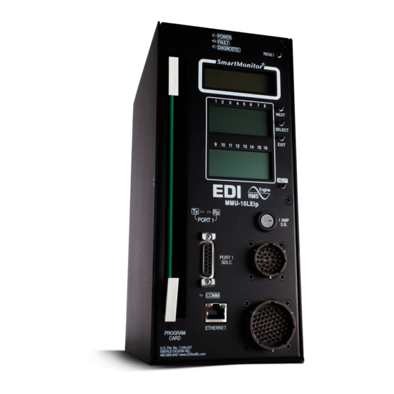
EDI SmartMonitor MMU-16LE Series Manuals
Manuals and User Guides for EDI SmartMonitor MMU-16LE Series. We have
1
EDI SmartMonitor MMU-16LE Series manual available for free PDF download: Operation Manual
EDI SmartMonitor MMU-16LE Series Operation Manual (56 pages)
NEMA TS-2 Enhanced Malfunction Management Unit
Brand:
EDI
| Category:
Measuring Instruments
| Size: 1 MB
Table of Contents
Table of Contents
3
Section 1 General
7
Description
7
Advanced Feature Overview
7
Liquid Crystal Status and Field Display
7
Menu Driven Operation
7
Context Sensitive Help System
7
Set-Up Wizard
7
Diagnostic Wizard
7
Program Card Memory
8
RMS Voltage Reporting
8
Eccom Software Interface
8
Nema TS-1 Operation with SDLC Mode
8
Flashing Yellow Arrow (FYA) Protected-Permissive Movement
8
Five Section Arrow Suppression Protected-Permissive Movement (PPLT5)
9
General
9
Field Signal Terminals
10
Ledguard
10
LED Field Signal Sensing
10
Type Select Input
10
Type 12 with SDLC Mode
11
Force Type 16 Mode
12
Section 2 Standard Functions
13
Conflict Monitoring
13
Red Fail Monitoring
13
Red Enable Input
13
Walk Disable Option
13
Voltage Monitoring
14
24Vdc Supply Monitoring
14
24Vdc Monitor Inhibit Input
14
24Vdc Monitor Latch Input
14
24Vdc Monitor II 12Vdc Mode
14
Controller Voltage / Fault Monitor Input
14
CVM Monitor Latch Input
15
CVM Log Disable
15
Local Flash Status Input
15
Minimum Yellow Change / Red Clearance Monitoring
15
Minimum Yellow Change Interval
15
Minimum Yellow Clearance Disable
15
Minimum Yellow Plus Red Interval
15
Minimum Yellow Plus Red Clearance Disable
16
MMU Power Failure Detection
16
Port 1 Communications
16
Port 1 Timeout
17
Port 1 Disable Input
17
Type 129 Response Frame
17
Output Relay Recovery
18
Internal Diagnostics
18
Memory Diagnostics
18
Microprocessor Monitor
18
Internal Hardware Monitor
18
Section 3 Enhanced Features
19
Hardware Features
19
Dual Indication Monitoring
19
Walk Disable Option
20
External Watchdog Monitoring
20
Program Card Absent Indication
20
Reset Input Detection
20
Display LED Test
20
Recurrent Pulse Detection
21
Type Fault
21
Field Check Monitoring
22
Field Check Fault
22
Field Check Status
22
Diagnostic Wizard
23
Flashing Yellow Arrow Protected-Permissive Monitoring (FYA)
24
Basic FYA MODE
24
Compact Fyac MODE
25
Fyac Type 16 Mode
25
Fyac Type 12 Mode
26
FYA Channel Assignment Diagrams
27
Five Section Arrow Suppression Protected-Permissive Monitoring (PPLT5)
28
Basic PPLT5 Arrow Suppression Mode
28
PPLT5 Arrow Suppression Channel Assignment Diagrams
30
Section 4 Eccom Interface
31
EDI Eccom Monitor Reports
31
General Data
31
Current Status (S)
31
Previous Fault (PF) Event Log
31
AC Line (AC) Event Log
31
Manual Reset (MR) Event Log
32
Configuration (CF) Event Log
32
Signal Sequence Event Log
32
Configuration Programming
32
Eccom Configuration Set-Up Wizard
32
Ethernet LAN Port
32
Section 5 Menu Operation
33
Main Status Menu
33
Top Level Menu
33
Status
33
Menu
34
View Logs
34
View and Set Configuration
34
Set-Up Wizard
34
Clear Logs
35
Set Clock
35
Section 6 Installation
36
General
36
Program Card Programming
36
Permissive Channel Programming
36
Minimum Flash Time Programming
37
Minimum Yellow Change Disable Programming
37
Voltage Monitor Latch Programming
37
Enhanced Function Programming
38
Field Check Enable Programming
38
Dual Indication Enable Programming
38
Red Fail Enable Programming
38
Unit Option Programming
39
Recurrent Pulse Option
39
Walk Disable Option
39
Log CVM FAULTS Option
39
External Watchdog Enable Option
39
II = 12 VDC Enable Option
39
Program Card Memory Enable Option
39
Ledguard Enable Option
39
Force Type 16 Mode Enable Option
39
Type 12 with SDLC Mode Enable Option
39
View Program Card Options
40
Yellow Plus Red Clearance Disable Programming
40
View Monitor ID and Name
40
View Firmware Version
40
Run the Setup Wizard
40
Set Factory Default Programming
40
Set ATSI Default Programming
41
View Configuration Check Value
41
Flashing Yellow Arrow Monitor
41
PPLT5 Arrow Suppression Monitor
41
Set-Up Wizard
42
Unused Channels
42
Pedestrian Channels
42
Protected-Permissive Turn Channels
43
Review Channel Assignments
43
Section 7 Front Panel Description
44
Main Status Display
44
Channel Status Display
44
Front Panel LED Indicators
44
Power Indicator
44
Fault Indicator
44
Diagnostic Indicator
44
Receive Indicator
44
Transmit Indicator
44
COMM Indicator
44
Front Panel Buttons
45
Reset Button
45
Menu Control Buttons
45
Next Button
45
Select Button
45
Exit Button
45
Help Button
45
Section 8 Specifications
46
Electrical
46
Power Requirements
46
AC Voltage Monitors
46
Power Fail Monitor
46
DC Voltage Monitor
46
Logic Inputs
46
Mechanical
46
Environmental
47
Section 9 Timing Functions
48
Section 10 Wiring Assignments
49
Harnessing Connectors
49
Type 16 Terminations
49
Type 16 Connector MS-A Pin Terminations
49
Type 16 Connector MS-B Pin Terminations
50
Type 12 Terminations
51
Type 12 Connector MS-A Pin Terminations
51
Type 12 Connector MS-B Pin Terminations
52
MMU16LE-RM & Mmu16Leip-RM Rack Mount Connector
52
Programming Card Pin Connections
53
Programming Card P1 Connector
53
Programming Card P2 Connector
54
Port 1 Connector
55
EIA-232 Connector
55
EIA-232 Cable to a PC
56
Ethernet LAN Port (J2)
56
Ethernet LAN Cable
56
Advertisement
Advertisement
Related Products
EDI SmartMonitor MMU-16LEip
EDI SmartMonitor MMU2-16LE Series
EDI SmartMonitor MMU2-16LEip
EDI MX Series
EDI 2010
EDI 2010ECL
EDI 2010ECLip
EDI 2018ECL
EDI 2018ECLip
EDI 210E
EDI Categories
Measuring Instruments
Monitor
Test Equipment
Industrial Electrical
Cash Counter
More EDI Manuals
Login
Sign In
OR
Sign in with Facebook
Sign in with Google
Upload manual
Upload from disk
Upload from URL