Table of Contents
Advertisement
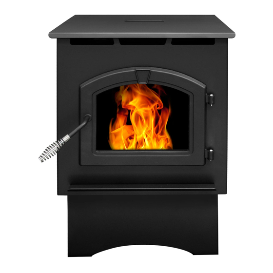
PH50PS-B - LARGE PELLET STOVE WITH PEDESTAL AND BASE PAN
PH35PS-B
SAFETY NOTICE: PLEASE READ THIS ENTIRE MANUAL BEFORE INSTALLATION AND USE OF
THIS PELLET FUEL BURNING ROOM HEATER. FAILURE TO FOLLOW THESE INSTRUCTIONS
COULD RESULT IN PROPERTY DAMAGE, BODILY INJURY OR EVEN DEATH. CONTACT
LOCAL BUILDING OFFICIALS ABOUT RESTRICTIONS AND INSTALLATION INSPECTION
REQUIREMENTS IN YOUR AREA.
Questions, problems, missing parts? Before returning to your retailer, call our customer
service department at 877-447-4768 8:30 a.m – 4:30 p.m. CST, Monday – Friday or email us at
customerservice@ghpgroupinc.com.
6440 W. Howard St.
Niles, IL 60714
877-447-4768
Owner's Manual
Installation and Operation
High Efficiency Pellet Stove
PH35PS-B - MEDIUM PELLET STOVE WITH PEDESTAL
PH50CABPS-B - CABINET PELLET STOVE
SAVE THESE INSTRUCTIONS
PH35PS-B, Emissions
Report No: 0061PS095E
7077-801F • 08/20
MODELS:
PH50PS-B
PH50PS-B & PH50CABPS-B,
Emissions Report No: 19-470
PH50CABPS-B
Certified to ULC S627
and ASTM E1509
Advertisement
Table of Contents

Related Manuals for pleasant hearth PH35PS-B


Summary of Contents for pleasant hearth PH35PS-B
- Page 1 Owner’s Manual Installation and Operation High Efficiency Pellet Stove MODELS: PH35PS-B - MEDIUM PELLET STOVE WITH PEDESTAL PH50PS-B - LARGE PELLET STOVE WITH PEDESTAL AND BASE PAN PH50CABPS-B - CABINET PELLET STOVE PH35PS-B PH50PS-B PH50CABPS-B SAFETY NOTICE: PLEASE READ THIS ENTIRE MANUAL BEFORE INSTALLATION AND USE OF THIS PELLET FUEL BURNING ROOM HEATER.
- Page 2 Lighting Instruction Guide CAUTION Follow all instructions and warnings for safe startup of stove. Failure to follow instructions could result in injury or damage. During startup and normal operation your appliance’s front door must be closed. Odors and vapors are released during initial startup after purchase. Burning your appliance on HI for 30 minutes will allow the paint to cure.
-
Page 3: Table Of Contents
G. Non-Combustible Materials ....6 A. Appliance Dimensions: PH35PS-B ......24 H. Combustible Materials ......6 B. - Page 4 CAUTION IMPORTANT After reading these instructions, if you have any doubt It is highly recommended that the pellet heater and about your ability to complete your installation in a chimney be installed by a qualified installer. A qualified professional manner you should obtain the services installer is a person or entity who regularly installs solid of an installer versed in all aspects as to the correct burning fuel products and chimneys in the course of their...
-
Page 5: Listing And Code Approvals
* Weighted average LHV (Low Heating Value) efficiency using data collected during EPA emissions tests in accordance with the requirements of CSA B415.1. The PH35PS-B, PH50PS-B & PH50CABPS-B ** Weighted average HHV (High Heating Value) efficiency is Certified to comply with 2020 particulate using data collected during EPA emissions tests in emission standards. -
Page 6: Glass Specifications
E. Electrical Rating (On High) stove input, if the stove exceeds the room size, outside air must be installed. Model Electrical Rating J. California - PROP65 PH35PS-B 115 VAC, 60 Hz, Start 2.6 Amps, PH50PS-B Run 0.9 Amps WARNING PH50CABPS-B This product and the fuels used to operate this product (wood), and F. -
Page 7: General Information
General Information A. Fire Safety Clinkers Minerals and other non-combustible materials such as To provide reasonable fire safety, the following should be sand will turn into a hard, glass-like substance called a given serious consideration: clinker when heated in the firepot. •... -
Page 8: General Operating Information
General Operating Information NOTICE: If you expect that children may come into contact WARNING with this appliance, we recommend a barrier such as a decorative screen (See your retailer for suggestions). HOT SURFACES! Glass and other surfaces are hot during operation AND cool down. -
Page 9: User Dial Control
B. User Dial Control The appliance has one dial control located on the side of the unit used for daily operation. There are four primary settings on this dial. • Off: - When the dial indicator is in the off position the unit will go into a shut down and remain off until the dial is turned to one of the other three settings. -
Page 10: Priming The Feed Tube
D. Priming the Feed Tube If the appliance does not ignite, the LED light will blink red four times showing a missed ignition alarm. Turn the appliance to STOP! off and remove and EMPTY the firepot. Return the firepot to the appliance in the correct orientation. Please Read Prior to Attempting Prime See figure in Cleaning Fire pot in the General Maintenance Function... -
Page 11: Fire Characteristics
H. Fire Characteristics The overall height of the flame will vary throughout the burn for a couple of reasons. First is that the flame will vary based on type of fuel or even batch of fuel. Secondly, the appliance adjusts the burn rate according to the how far away the room temperature is from the set temperature. -
Page 12: Led Color Coding Chart And Explanation
N. LED Color Coding Chart and Explanation Number of Flashes between Description Notes Color pauses When priming the feed system and filling the Steady ON while firepot, DO NOT OVERFILL FIREPOT FOR priming feed tube Feed Motor is running continuously. Green (max time 2 (This primes the feed tube). -
Page 13: Maintaining & Servicing Your Appliance
Maintaining & Servicing Your Appliance When properly maintained, your appliance will give you CAUTION many years of trouble-free service. Contact your GHP dealer to answer questions regarding proper operation, Shock and Smoke Hazard troubleshooting and service for your appliance. • Smoke spillage into room can occur if A. -
Page 14: General Maintenance
C. General Maintenance 1. Types of Fuel The type of fuel you are burning will dictate how often you have to clean your firepot. If the fuel you are burning has a high dirt or ash content, it may be necessary to clean the firepot more than once a day. - Page 15 4. Disposal of Ashes 6. Cleaning the Hopper • Frequency: As needed • Frequency: Monthly or after burning 25 bags of fuel • By: Homeowner • By: Homeowner Ashes should be placed in a metal container with a tight- After burning approximately 25 bags of fuel you will need to fitting lid.
- Page 16 7. Cleaning the Exhaust Path, Baffles & Drop Tube 9. Cleaning Convection Blower - Requires No Lubrication • Frequency: Monthly or every 25 bags or more frequently • Frequency: Monthly depending on Dust/Dirt build-up depending on ash build-up. • By: Homeowner •...
-
Page 17: High Ash Fuel Content Maintenance
11. Preparing Firebox for Non-Burn Season • Frequency: Yearly Les granules sont refoulées dans Les granules sont refoulées dans • By: Homeowner le tuyau d’alimentation le tuyau d’alimentation a. Be sure the appliance is allowed to cool, has been Accumulation unplugged and the exhaust blower is off. -
Page 18: Frequently Asked Questions
E. Frequently Asked Questions Why is there a black residue building up on the outside of my home? What causes my glass to become dirty? Wind can cause this to happen. If the appliance is operating If the glass has white ash build up it is normal and the correctly very little soot should ever exit the termination cap. -
Page 19: Replacement Parts
Replacement Parts A. Convection Blower Replacement B. Exhaust Blower Replacement 1. Turn the dial control to the off position. Unplug the power 1. Turn the dial control to the off position. Unplug the power to the unit. to the unit. 2. -
Page 20: Snap Disc Replacement
C. Snap Disc Replacement D. Igniter Replacement Power - Manual Reset 1. Turn the dial control to the off position. Unplug the power to the unit. 1. Turn the dial control to the off position. Unplug the power to the unit. 2. -
Page 21: Glass Replacement
F. Glass Replacement I. Feed Motor Replacement 1. Turn the dial control to the off position and unplug the WARNING unit. Remove the right side panel and feed motor cover plate in the rear of the unit. • Glass is 5mm thick high temperature 2. -
Page 22: Getting Started
Consideration must be given to: Model Weight of Appliance • Safety, convenience, and traffic flow PH35PS-B 153 lbs. (69.5kg) • Placement of the chimney and chimney connector and PH50PS-B 192 lbs. (87kg) to minimize the use of chimney offsets. -
Page 23: Draft
Minimum Vacuum MODEL Requirements • Remove appliance and components from packaging and inspect for damage. PH35PS-B 0.17 inches W.C. • Report to your dealer any parts damaged in shipment. PH50PS-B 0.17 inches W.C. • Read all the instructions before starting the PH50CABPS-B 0.17 inches W.C. -
Page 24: Dimensions & Clearances
Dimensions & Clearances A. Appliance Dimensions: PH35PS-B B. Appliance Dimensions: PH50PS-B 21-3/4 [552] 23-3/4 [603] 3-1/2 [102] [89] 24-5/16 21-15/16 [617] [558] [762] [864] 4-1/8 4-1/8 [104] [105] 26-13/16 [681] 30-13/16 [783] [305] [330] 19-7/8 [505] 24-3/8 [620] 7077-801F • 08/20... -
Page 25: Appliance Dimensions: Ph50Cabps-B
C. Appliance Dimensions: PH50CABPS-B D. Clearances to Combustibles (UL and ULC) 23-3/4 [603] 4-1/2 [114] 23-3/16 [590] Vertical Installations (Interior Flue) Straight Back Against Wall Inches Millimeters Back Wall to Appliance Back Wall to Flue Pipe Side Wall to Appliance Corner Installation Inches Millimeters... -
Page 26: Hearth Pad Requirements (Ul And Ulc)
E. Hearth Pad Requirements (UL and ULC) Use a non-combustible floor protector, extending beneath appliance and to the front, sides and rear as indicated. Measure front distance “M” from the surface of the glass door. Must extend 2 inches (51mm) beyond each side of pipe (shaded area) *Exception for Horizontal Installations: CANADA INSTALLATIONS: A non combustible floor... -
Page 27: Vent Information
Vent Information A. Chimney and Exhaust Connection B. Venting Termination Requirements 1. Chimney & Connector: Use 3 or 4 inch (76-102mm) CAUTION diameter type “L” or “PL” venting system. It can be vented vertically or horizontally. 2. Mobile Home: Approved for all Listed pellet vent. If Do not terminate vent in any enclosed or semi-enclosed area such as a carport, garage, attic, crawl space, under using the 3 inch (76mm) vertical Top Vent Adapter Kit... -
Page 28: Equivalent Feet Of Pipe
C. Equivalent Feet of Pipe WARNING The table below can help you calculate the equivalent feet of pipe which is a method used to determine pellet vent size. Vent surfaces get HOT, can cause burns if touched. Non-combustible shielding or guards may be required. Example of 3 Elbow-Rear Vent Termination Calculation PELLET FEET... -
Page 29: Pellet Venting Charts
E. Pellet Venting Charts WARNING The maximum horizontal venting allowed with no vertical venting attached is 48 inches (1219mm) including one Fire Risk. 90° elbow or two 45° elbows. This is our recommended • Only LISTED venting components may be horizontal venting installation. -
Page 30: Vertical - Interior - Typical Installation
Vent Systems A. Vertical - Interior - Typical Installation C. Vertical into Existing Class A Chimney PREFERRED METHOD #1 Rain Cap Rain Cap Flashing 12 in. (305mm) Minimum 12 in. Flashing (305mm) Minimum Firestop Firestop 6 in. (152mm) Class A Chimney Connector Adapter Ceiling Support... -
Page 31: Masonry
D. Masonry Fireclay flue Concrete Cap Liner with Airspace Flashing 1 in. (25mm) Clearance with Firestop 1 in. (25mm) Clearance 3 in. (76mm) Minimum 6 in. (152mm) Minimum Sheathing Clean-Out Airtight Clean-Out Door Non-combustible Hearth Pad E. Alternate Masonry Fireclay Flue Liner Concrete Cap with Airspace Flashing... -
Page 32: Through The Wall
F. Through The Wall NOTE: In Canada, where passage through a wall or Horizontal termination cap must be a minimum of 6 partition of combustible construction is desired, the installation shall conform to CAN/CSA-B365 inches. (152mm) from the wall. Approved for mobile home installations. -
Page 33: Mobile Home
Mobile Home A. Mobile Home Installation CAUTION You must use an authorized Outside Air Kit for installation in a mobile home. THE STRUCTURAL INTEGRITY OF THE MOBILE 1. An outside air inlet must be provided for the combustion HOME FLOOR, WALL AND CEILING/ROOF MUST air and must remain clear of leaves, debris, ice and/or BE MAINTAINED snow. -
Page 34: Appliance Set-Up
Appliance Set-Up A. Outside Air Kit Instructions B. Power up the Unit An outside air kit has been provide standard with the Plug the unit into 120VAC power. appliance. It is highly recommended to use the outside air CAUTION kit for maximum performance and to reduce effects from negative pressure in the home. -
Page 35: Troubleshooting
Troubleshooting With proper installation, operation, and maintenance your appliance will provide years of trouble-free service. If you do experience a problem, this troubleshooting guide will assist a qualified service person in the diagnosis of a problem and the corrective action to be taken. This troubleshooting guide can only be used by a qualified service technician. Symptom Possible Cause Corrective Action... - Page 36 Symptom Possible Cause Corrective Action Dirty exhaust and/or venting system. Check for ash build up in unit, including behind rear panels, firebox, exhaust blower and venting. Slow or smoky Not enough combustion air Adjust the trim start-up and/or lazy flame Misaligned igniter Center the igniter in the chamber Wet fuel / poor quality fuel...
- Page 37 Following correction of any Alarm, turn the dial control to the OFF position, wait 10 seconds and turn back to desired setting OR unplug the unit, wait 10 seconds then restore power. Alarm Possible Cause Corrective Action (LED Flashing RED) No fuel is delivered to the firepot to Fill the hopper, inspect the feed tube for jams, sustain flame...
-
Page 38: Reference Materials
Reference Materials A. Component Function When describing the location of a 1. Control Board component, it is always AS YOU FACE THE FRONT OF THE APPLIANCE. The control board is located on the right side of the appliance behind the lower right side panel. 11. -
Page 39: Wiring Diagram
B. Wiring Diagram IGNITER VACUUM HOPPER FEED MOTOR SWITCH SWITCH EXHAUST BLOWER CONVECTION BLOWER NEUTRAL 110 V LINE SNAP DISC FUSE EXHAUST TEMPERATURE AMBIENT TEMPERATURE SERIAL PORT (SERVICE ONLY) POT SET TEMP VCC POT SET TEMP GND POT SET TEMP SIG POT FEED ADJUST VCC POT FEED ADJUST GND POT FEED ADJUTS SIG... -
Page 40: Replacement Parts
C. Replacement Parts 10 12 12.7 12.6 12.5 12.4 12.3 12.2 12.1 Hopper Lid (1 per unit) Feed Assembly Side Panels (2 per unit) 12.1 Bronze Bushings (2 per unit) Front Door Assembly 12.2 Auger Assembly 3.1 Spring handle and hinge pins 12.3 Feed Motor Hitch Pin 3.2 Door Rope Gasket and Glass Tape 12.4 Feed Motor Bracket... -
Page 41: Service & Maintenance Log
D. Service & Maintenance Log Date of Service Performed By Description of Service customerservice@ghpgroupinc.com 7077-801F • 08/20... -
Page 42: Year Warranty
Do not use ammonia based cleaners. A suitable cleaner is or masonry wood insert is free from manufacturing and material defects for a available at your nearest Pleasant Hearth dealer. DO NOT CLEAN GLASS period of five years from the date of sale, subject to the following conditions WHILE HOT AND DO NOT USE ABRASIVE CLEANERS. - Page 43 customerservice@ghpgroupinc.com 7077-801F • 08/20...
- Page 44 CONTACT INFORMATION: 6440 W. Howard St. Niles, IL 60714 877-447-4768 Please contact the GHP Group with any questions or concerns. www.ghpgroupinc.com For Customer Service 1-877-447-4768 Prior to calling, please have the model, serial number, and sales receipt of the unit you are calling about.
Need help?
Do you have a question about the PH35PS-B and is the answer not in the manual?
Questions and answers
how do you change the snap disk no room to get to second screw
The manual does not provide specific instructions for changing the snap disk when there is no room to access the second screw. However, the general procedure for snap disk replacement is:
1. Turn the dial control to the off position and unplug the power to the unit.
2. Use a screwdriver to remove the two 6-32 fasteners retaining the snap disk onto the side of the feed tube.
3. Attach the new snap disk using the same fasteners.
4. Re-attach the wire leads.
5. Restore power.
If access to the second screw is blocked, you may need to move or disassemble nearby components to create space.
This answer is automatically generated
Where can I see your wood stoves ? I live in Langhorne Pennsylvania