Advertisement
SRi-625G COMPLIANT HIGH VOLUME LOW PRESSURE
IMPORTANT: Before using this equipment,
read all safety precautions and instructions.
Keep for future use.
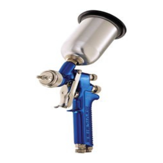
DESCRIPTION
The SRI is a small gravity fed spray gun
designed for spraying spot repairs and small
areas. The gun can spray from a small
round to a 6" fan pattern (according to
setup). This product is suitable for use with
both water-based and solvent-based coating
materials.
SPECIFICATIONS
Air Supply
Connection:
Universal 1/4" BSP
and NPS (M)
Maximum Static
Air Inlet Pressure: P
= 7 bar (130 psi)
1
Nominal Gun Air
Inlet Pressure (with
Gun Triggered):
2 bar (29 psi)
Gun Weight (with
Cup and Lid):
390g (13.76 oz.)
MATERIALS OF CONSTRUCTION
FOR WETTED PARTS
Gun Body:
Anodized Aluminum
Nozzle:
303 Stainless Steel
Needle:
303 Stainless Steel
Cups:
Nylon and Aluminum
Cup Lid:
Polypropylene
This gun was manufactured to provide a
maximum transfer efficiency by limiting air
cap pressure to 10 psi (complies with rules
issued by SCAQMD and other air quality
authorities).
This gun will produce approximately 10
psi air cap pressure at 29 psi gun inlet
pressure. An air cap test kit is available
(see Accessories) which can be utilized to
set the exact air cap presssure. Air con-
sumption for the SRI-625G is 4.5 SCFM at
10 psi cap pressure.
This gun comes with both a 4 oz. aluminum
gravity cup and lid and a 4 oz. nylon
disposable cup and lid.
GRAVITY FEED SPOT REPAIR SPRAY GUN
This gun includes 303 series
stainless steel fluid tip and
needle. This gun should not be
used with chlorinated solvent
materials. See page 2 for poten-
tial hazards.
Important: This gun may be used with most
common coating and finishing materials. It
is designed for use with mildly corrosive
and non-abrasive materials. If used with
other high corrosive or abrasive materials,
it must be expected that frequent and thor-
ough cleaning will be required and the ne-
cessity for replacement of parts will be in-
creased.
INSTALLATION
For maximum transfer efficiency, do not
use more pressure than is necessary to
atomize the material being applied.
1.
Connect the gun to a clean, moisture
and oil free air supply. Fully open air
flow valve (20). Install an air cap test kit
over tip. When gun is triggered on,
adjust regulated pressure to desired
setting to provide a maximum of 10 psi
at the air cap. Do not use more pres-
sure than is necessary to atomize the
material being applied. Excess pres-
sure will create additional overspray
and reduce transfer efficiency.
If quick connects are required, use
only high flow quick connects ap-
proved for HVLP use such as DeVil-
biss HC-4419 and HC-4719. Other
types will not flow enough air for
proper gun operation.
If an air adjusting valve is used at the
gun inlet, use DeVilbiss Model HAV-
500 or HAV-501. Some competitive
adjusting valves have significant
pressure drop that can adversely
affect spray performance. Models
HAV-500
minimal pressure drop, which is
important for HVLP spraying.
2 .
Attach the gravity feed cup to the
material inlet.
NOTE
NOTE
NOTE
and
HAV-501
have
SERVICE BULLETIN
SB-2-510-B
Replaces SB-2-510-A
Repair Kit SRI-426
NOTE
Protective coating and rust inhibi-
tors have been used to keep the
gun in good condition prior to ship-
ment. Before using the gun, flush
it with solvents so that these ma-
terials will be removed from fluid
passages.
OPERATION
Mix, prepare and strain the material to be
sprayed according to the paint maufacturer's
instructions.
Strain material through a 60 or 90 mesh
screen.
1.
Fill the gravity feed cup with the mate-
rial. Do not overfill. Make sure that the
cup lid vent hole is clear.
2.
Open the spreader adjustment valve
(6) (Fan) by turning the valve stem
counterclockwise.
3.
Close the fluid needle adjusting screw
(12) by turning clockwise.
4.
Turn on air supply and set gun inlet
pressure to lowest recommended pres-
sure for material being sprayed. Best
atomization will occur with 10 psig air
cap pressure. However, some materi-
als can be sprayed at lower pressures,
improving transfer efficiency.
5.
Spray a test area by turning fluid needle
adjusting screw (12) counterclockwise
until a full coat is obtained.
If the finish is too sandy and dry, the
material flow may be too low for the
atomization air pressure being used.
If the finish sags, there is too much material
flowing for the atomization air pressure
being used.
Both of the above can be corrected by
increasing or decreasing the atomization air
pressure or the material flow. Pattern width
can be altered by turning spreader adjust-
ment valve (6), either clockwise to decrease
the width or counterclockwise to increase
the width.
See Spray Gun Guide, SB-2-001 latest
revision, for details concerning setup of
spray guns.
Advertisement
Table of Contents

Related Manuals for DeVilbiss SRi-625G


Summary of Contents for DeVilbiss SRi-625G
- Page 1 Air con- If an air adjusting valve is used at the pressure or the material flow. Pattern width sumption for the SRI-625G is 4.5 SCFM at gun inlet, use DeVilbiss Model HAV- can be altered by turning spreader adjust- 10 psi cap pressure.
-
Page 2: Safety Precautions
Page 2 SB-2-510-B SAFETY PRECAUTIONS This manual contains information that is important for you to know and understand. This information relates to USER SAFETY and PREVENTING EQUIPMENT PROBLEMS. To help you recognize this information, we use the following symbols. Please pay particular attention to these sections. -
Page 3: Preventive Maintenance
.039 SRI-37 SRI-2-08-K* .031 *Includes (1) SRI-6 fluid tip seal. NOTE: SRI-625G only comes with the 1.0 mm tip and needle installed. PREVENTIVE MAINTENANCE SPRAY GUN LUBRICATION PARTS REPLACEMENT To clean air cap and fluid tip, brush exterior Daily, apply a drop of SSL-10* spray gun SRI-411 Packing Replacement Instructions with a stiff bristle brush. -
Page 4: Parts List
Page 4 SB-2-510-B Views showing correct Air Cap/Retaining Ring assembly. Fig. B Fig. A Provided Cups/ Lids: #22 Nylon Cup (1) Fluid Tip (Torque to with Lid (1) 6-7 ft-lbs.) PLUS #23 Aluminum Cup (1) with Lid (1) Air Inlet Nipple (Torque to 15 ft-lbs.) Use medium strength thread sealant... - Page 5 SB-2-510-B Page 5 TROUBLESHOOTING CONDITION CAUSE CORRECTION Horn holes plugged. Clean. Ream with non-metallic point. Heavy top or Obstruction on top or bottom of fluid tip. Clean. bottom pattern Cap and/or tip seat dirty. Clean. Left or right side horn holes plugged. Clean.
- Page 6 Yellow Pages under "Automobile Body Shop Equipment and Supplies". If further assistance is required, write or call one of the following DeVilbiss Distribution Centers or Sales Offices nearest you. FOR TECHNICAL ASSISTANCE, CALL TOLL FREE 1-800-445-3988 (U.S. AND CANADA ONLY).
Need help?
Do you have a question about the SRi-625G and is the answer not in the manual?
Questions and answers