Table of Contents

Related Manuals for Zida P845SD


Summary of Contents for Zida P845SD
- Page 1 SER’S More compatible, more functional and more competitive. MANUAL Excellent quality and faster response. Supporting Intel Pentium IV FC-PGA2 Processor in the 478Pin package. UDMA33/66/100, PC133 SDRAM Quality, Performance Mainboards...
- Page 2 No part of this manual, including the products and software described in it, may be reproduced, transmitted, transcribed, stored in a retrieval system, or translated into any language in any form or by any means, except documentation kept by the purchaser for backup purposes, without the express written permission of MANUFACTURER.
-
Page 3: Table Of Contents
Contents Table Of Contents Overview ........5 Fast Start Installation . -
Page 5: Overview
Overview Thank You for purchasing our High Performance Mainboard. Our advanced technology mainboard is designed for processing speeds of 1.7G or above and is upgradeabled for future processors. The Intel Mainboard Utilizes 82845 and ICH2 chipset provide an Integrated Bus Mastering IDE controller with two high performance IDE interfaces for up to four UDMA IDE devices (hard drives, or CD-ROM's). -
Page 6: Fast Start Installation
Fast Start Installation This section will aid you in quickly setting up the Mainboard. Be sure to take caution to avoid personal injury or damage to wiring due to sharp pins on connectors, printed circuit assemblies, rough edges and corners and hot components. Your Location Requirements Are: •... -
Page 7: Checking The Package Contents
Checking The Package Contents Remove the items from the box and make sure you have the following items before beginning. If any of the items below are missing, please contact the representative for part replacement. Micro ATX Box Standard Package 1) Mainboard 2) Driver CD with Norton AntiVirus 2001 OEM Version 3) User Manual... -
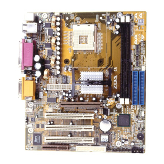
Page 8: Mainboard Diagram
Mainboard Diagram Page 8 Mainboard User's Manual... - Page 9 Before we begin installing your series Mainboard, we have provided you with a diagram of the Mainboard to help you locate the appropriate “connectors”. The letters below describe the key Mainboard components. Page number in the right hand column will direct you to detailed description of the component. P845SD Option : AC97 2.1 Compliant 3D Audio Onboard...
-
Page 10: Jumper Settings
Jumper settings Set the Jumper JP2 [1-2] Normal; [2-3] to clear CMOS. Page 10 Mainboard User's Manual... -
Page 11: Quick Steps
7 Quick Steps Please follow these steps in order to assure that your series of Mainboard installation is successful. Please refer to the back chapters for further information regarding boot-up and configurations. An anti-static wrist band is recommended when handling electronic components, be sure your work area is static free before you begin this section. - Page 12 CAUTION! Be sure that this MB cann't support Cyrix sufficient air circulation must be available across the processor’s heatsink. Without sufficient circulation, the processor could overheat and damage both the processor and the mainboard. You may install an auxiliary fan if necessary. Page 12 Mainboard User's Manual...
-
Page 13: Installing The Memory
Installing the Memory Memory is installed in DIMM Sockets 1-2 (F Mainboard in diagram) as follows : After you have set the DIMM firmly into its socket, snap the white chip holders up to lock in the DIMM. Mainboard User's Manual Page 13... -
Page 14: Attaching Atx Power Supply
Attaching ATX Power Supply. ATX Power Supply Connector (20-pin ATX PWR and 4Pin +12V). The single 20-pin connector (B in mainboard diagram) incorporates standard +/-5V and +/-12V, with a standby 5V and +3.3V. With a power supply that supports remote power on/off, the mainboard can turn off the system power through the software control, such as the shutdown in Windows 95 Start Menu. -
Page 15: Floppy Disk Drive Connector
Floppy Disk Drive Connector (34-pin FLOPPY). This is a 34-pin connector that supports the provided floppy drive ribbon cable. After connecting the single end to the on-board “FLOPPY” connector, (O in mainboard diagram) connect the remaining plugs on the other end to the corresponding floppy drives. -
Page 16: Mounting Mainboard To Chassis
Mounting Mainboard to chassis Snap black mounting pins onto the mainboard as shown. Carefully install the mainboard into the computer chassis and align the corresponding mounting holes on the mainboard with the holes on you chassis. While chassis design varies you may need to refer to the chassis manual for the mainboard Insert white pins through the chassis and... -
Page 17: Installing Add-In Boards
Installing Add-in Boards First read your expansion card documentation for hardware and software settings that may be required to set up your specific card. Set any necessary jumpers on your expansion card and remove the cover plate on your computer case at the slot you intend to use. - Page 18 Make sure to align rear external I/O connector's with the corresponding openings in chassis shown below (A,C & G in mainboard diagram) You can now attach the Front Panel Function Connector (M in mainboard diagram) wires Keyboard, Mouse and Monitor cables to the appropriate ports.
-
Page 19: Bios Setup
BIOS Setup... - Page 20 Award BIOS Setup Standard CMOS Features Sets time, date, hard disk type, types of floppy drive. Monitor type, and if keyboard is installed. Advanced BIOS Features Sets Typematic Rate and Delay, Above 1 MB Memory Test, Memory Test Tick Sound, Hit <Del> Message Display, System Boot Up Sequence, and many others.
- Page 21 Standard CMOS Features Select the BIOS Setup options by choosing Standard CMOS Features from the BIOS. Standard Setup options are described below. Date (mm:dd:yy) - Setting for the system Date Time (hh:mm:ss) - Setting for the system Time. Primary Master Primary Slave Secondary Master Secondary Slave...
- Page 22 Advanced BIOS Features Virus Warning You can "Enable" or "Disable" this feature. When enabled, BIOS will activate automatically if anything attempt to access the boot sector or hard disk partition table during system boot-up. The default value is "Disabled". CPU L1 & L2 Cache This category enables or disables the CPU to speed up memory access.
- Page 23 Boot Other Device This feature allows you to select other boot device automatically. Swap Floppy Drive This feature allows you to enable the system swap floppy function, the default is "Disabled". When this function enables, the system will assign the Drive A as Drive B, and vice versa. Boot Up Floppy Seek This default setting is "Enabled", so that the BIOS will search for floppy disk drive during boot up.
- Page 24 Typematic Delay (Msec) When holding down a key, the time between the first and second character display, this option specifies the numbers of times of character repeat on the screen. The default setting is "250". Security Option This option limits the access to the system and Setup or just to Setup. When you select "System", the system will not boot and access to CMOS Setup.
- Page 25 Advanced Chipset Features Choose Chipset Features Setup on the Setup main menu. All Chipset Setup options are then displayed. DRAM Timing Selectable Set DRAM Timing setting methor Available settingure by SPD Manual ,Default is By SPD. CAS Latency Time Specifies the number of SCLKS between the time when the Read command is sample by SDRAM and the whitney sample reads data from SDRAM ,Available settings are 2 (SCLKS) and 3.
- Page 26 Active to Precharge Delay The Field sets SDRAM active to precharge delay timing. the choices:5, 6, 7. DRAM RAS# to CAS# Delay This field sets the RAS to CAS Delay timing. The choices : 2, 3. DRAM RAS# Precharge This field sets the RAS Precharge timing. The choices : 2, 3.
- Page 27 Video BIOS Cacheable Select "Enabled" allows caching of the video BIOS, resulting in better system performance. However, if any program writes to this memory area, a system error may result. Video RAM Cacheable Select"enable" allows cachiag of the video RAM, Resulting in better system performance.
- Page 28 Integrated Peripherals On-Chip Primary / Secondary PCI IDE The chipset contains a PCI IDE interface with support for two IDE channels. Select "Enabled" to activate the primary IDE interface. Select "Disabled" to deactivate this interface. The choices : Enabled, Disabled. IDE Primary / Seconday Master / Slave PIO The four IDE PIO (Programmed Input / Output) fields let you set a PIO mode (0-4) for each of the four IDE devices that the onboard IDE interface supports.
- Page 29 IDE Primary / Secondary Master / Slave UDMA Ultra DMA33 implementation is possible only if your IDE hard drive supports it and the operating environment includes a DMA driver (Windows 95 OSR3 or a third-party IDE bus master driver). If your hard drive and your system software both support Ultra DMA33/66/100, select Auto to enable BIOS support.
- Page 30 Onboard AC97 Control This option allows you to control the onboard AC97. The choices:Enable, Disable. IDE HDD Block Mode This item allows your hard disk controller to use the fast block mode to transfer data to and from your hard disk drive (HDD). Enabled IDE controller uses block mode.
- Page 31 Onboard Serial Port 1 / Port 2 This item allows you to determine access onboard serial port 1 / port 2 controller with which I/O address. The choices : 3F8/IRQ4, 2F8/IRQ3, 3E8/IRQ4, 2E8/IRQ3, Disabled, Auto. UART Mode Select This option specifies the mode of UART. The choices : Normal, IrDA, ASKIR.
- Page 32 Parallel Port Mode This option specifies the parallel port mode. The Optimal default setting is Normal. The Fail-Safe default setting is Disabled. The settings are SPP, EPP, ECP, ECP+EPP. EPP Mode Select This option specifies the Enhanced Parallel Port specification version number that is used in the system.
- Page 33 Power Management Setup Power Management This option enables the chipset power management and APM (Advanced Power Management) features. The settings are User Define, Min Saving or Max Saving. Video Off Method This determines the manner in which the monitor is blanked. V/H SYNC+Blank This selection will cause the system to turn off the vertical and horizontal synchronization ports and write blanks to...
- Page 34 Video Off In Suspend When enabled, this feature allows the VGA adapter to operate in a power saving mode. Options : Yes, No. Suspend Type This determines the suspend type. Options : Stop Grant, and Pwr On Suspend. MODEM Use IRQ This determines the IRQ in which the MODEM can use.
- Page 35 CPU THRM-Throttling This option specifies the throttle slow clock ratio. The settings are 87.5%, 75.0%, 62.5% 50.0%, 37.5%, 25.0%, 12.5%. The Optimal and Fail-Safe default settings are 50.0%. Power On by Ring An input signal on the serial Ring Indicator (RI) line (an incoming call from the modem) awakens the system from a soft-off state.
- Page 36 PnP/PCI Configurations Reset Configuration Data Normally, you leave this field Disabled. Select Enabled to reset Extended System Configuration Data (ESCD) when you exit Setup if you have installed a new add-on and the system reconfiguration has caused such a serious conflict that the operating system cannot boot.The choices : Disabled, Enabled.
- Page 37 PC Health Status CPU Warning Temperature Specifies CPU warning temperature value. Available options are 50℃/122℉,53℃/127℉,56℃/133℉,60℃/140℉, 63℃/145℉, 66℃/151℉, 70℃/158℉ and Disabled. Default setting is "Disabled". System Temperature. CPU Temperature Detect System and CPU temperature automatically. System FAN Speed CPU FAN Speed Detect Fan Speed Status automatically.
- Page 38 Frequency / Voltage Control CPU Clock Ratio Options : X8, X9, X10, up to X24. Auto Detect PCI Clk Options : Enabled / Disabled Spread Spectrum Options : Enabled / Disabled CPU Host / 3V66/PCI Clock Options: Default, 100/66/33MHz, 103/69/34MHz, 105/70/35MHz, 107/71/36MHz, 109/73/36MHz, 111/74/37MHz, 114/76/38MHz, 117/78/39MHz, 120/80/40MHz, 127/85/42MHz, 130/87/43MHz.
- Page 39 Load Fail-safe Defaults Fail-safe defaults contain the most appropriate values of the system parameters that allow minimum system performance. Mainboard User's Manual Page 39...
- Page 40 Load Optimized Defaults Selecting this field loads the factory defaults for BIOS and Chipset Features which the system automatically detects. Page 40 Mainboard User's Manual...
- Page 41 Set Supervisor / User password When you select this function, the following message will appear at the center of the screen to assist you in creating a password. Type the password, up to eight characters and press<Enter>. The new password will clear the previously entered password from CMOS Memory, you will be asked to confirm the Password.
- Page 42 Save & Exit Setup Type "Y" will quit the Setup Utility and Save the user setup value to RTC CMOS. Type "N" will return to Setup Utility. Page 42 Mainboard User's Manual...
- Page 43 Exit Without Saving Type "Y" will quit the Setup Utility and Without Saving the User setup Value. Type "N" will return to Setup Utility. Mainboard User's Manual Page 43...
-
Page 44: Glossary
Glossary... -
Page 45: A- Ps/2 Mouse & Keyboard Connector
Glossary PS/2 Mouse & Keyboard Connector The Mainboard provides two on-board PS/2 connectors, one for the keyboard, and one for the mouse. PS/2 devices all have a standard 6-pin round shape connector. If you are already using a PS/2 mouse or keyboard, simply plug them into the corresponding connector. -
Page 46: C Universal Serial Bus (Usb) Connector
About the Soft Touch Power Button In an ATX based system, the new soft touch power button replaces the main power switch that turns your system on and off. From an OFF state, you can switch the system ON by simply pressing the power button. -
Page 47: E Infra-Red (Ir) Header
Infra-Red (IR) Header The Mainboard provides a 5-pin header interface, IR for connection to a Hewlett Packard HSDSL-1000 compatible infrared (IrDA) transmitter/receiver. Connect IR to the front panel I/O IrDA connector provided with your system. Once the module is connected to the front panel I/O IrDA connector, Serial port 2 can be re-directed to the IrDA module. -
Page 48: H Accelerated Graphics Port [Agp] Connector
Accelerated Graphics Port [AGP] Connector The Mainboard provides an AGP slot compatible with the Accelerated Graphics Port specification. AGP compliant video cards offer a much higher throughput than equivalent PCI bus video cards. PCI currently only supports a 33MHz bandwidth, and can transport at peak rates up to 133MB/s over its 32 bit data bus. -
Page 49: N Flash Bios
Speaker EXTSMI Keylock PW_LED Sus-Led Reset PW_BN HD_LED Flash BIOS The Mainboard flash BIOS provides users with more flexibility in upgrading their mainboards. The flash BIOS can be easily reprogrammed via software. Floppy Drive Header The Mainboard provides a 34-pin connector that supports the included floppy drive ribbon cable. -
Page 50: Q- Wakeup-Link Header
Also, you may connect the two hard disk drives so that both become Masters, using one ribbon cable on the primary IDE header and one on the secondary IDE header. WAKEUP-LINK Header The Mainboard provides on WAKEUP-LINK header (WOL) used to connect an add-in Network Interface Card which has Wakeup capability. -
Page 51: U Audio & Joystick Connectors
CAUTION! Be sure that sufficient air circulation is available across the processor’s heatsink by regularly checking that your CPU fan is working. Without sufficient circulation, the processor could overheat and damage both the processor and the mainboard. You may install an auxiliary fan if necessary. -
Page 52: Cd Driver & Software Installation Guide
1. Boot up the Operating System ( Windows 95/98/NT/2000 ) 2. Put the CD Disc into the CD-ROM Drive and wait for Autorun 3. Select P845SD and click your Operating System Type 4. Follow the instructions and install suitable drivers... -
Page 53: Norton Antivirus Oem Version Setup Guide
Norton Anti-Virus OEM Version Setup Guide Step 1 : Load the Driver CD in CDROM and find the Norton AntiVirus 2001 "Install" Option. Step 2 : When CD finishes loading, press " Install Norton AntiVirus" to install the software. Mainboard User's Manual Page 53... - Page 54 Step 3 : Follow the installation procedures on screen. Step 4 : Select "Yes" and press "Finish" button to reboot computer. Mainboard User's Manual Page 54...
- Page 55 Guide Introduce INSTANT ON function: INSTANT ON is a Windows 98 ACPI sleep mode function. When recovering from sleep mode, the system is able, in just a few seconds, to retrieve the last “state” of the system before it went to sleep and recover to that state. The “state” is stored in memory (RAM) before the system goes to sleep.
- Page 56 How to put your system into Stand by mode ? There are two ways : 1. Choose the “Stand by” item in the “Shut Down Windows” area. A. Press the “Start” button and then select “Shut Down” B. Choose the “Stand by” item and Click “OK”...
- Page 57 2. Set the system ”power on” button to initiate sleep mode in Win95/98: A. Double click “My Computer” and then “Control Panel” B. Double click the “Power Management” item. Page 57 Mainboard User's Manual...
- Page 58 C. Select the “Advanced” tab and “Standby” mode in Power Buttons. Restart your computer to complete setup. Now when you want to enter sleep mode, just press the “Power on” button. How to recover from the sleep mode? There are four ways to “wake up” the system: 1.
- Page 59 Notice to INSTANT ON users : 1. ATX power supply requirement - comply with the ATX 2.01 - provide more than 720 mA 5V Stand-By current 2. SDRAM requirement - PC133 compliant. Page 59 Mainboard User's Manual...
Need help?
Do you have a question about the P845SD and is the answer not in the manual?
Questions and answers