Advertisement
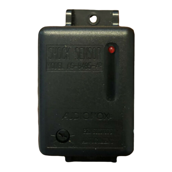
AS-9495-4P (NR)
AS-9495-4P (NR)
AS-9495-4P (NR)
AS-9495-4P (NR)
AS-9495-4P (NR)
MOUNTING THE SHOCK SENSOR:
MOUNTING THE SHOCK SENSOR:
MOUNTING THE SHOCK SENSOR:
MOUNTING THE SHOCK SENSOR:
MOUNTING THE SHOCK SENSOR:
Never mount the sensor outside the vehicle where it will be exposed to the elements. Never mount any compo-
nent near hot or moving parts. Always mount the components and route the wiring away from the rotating steering
shaft assembly. Always mount the sensor within 22" of the alarm module to assure the plug in cable reaches the
sensor.
1. Select a solid mounting location inside the vehicle. Ideally the inside firewall, center of the vehicle is best for
s e n s i t i v i t y. An alternate location can be the "A" pillar, " B " p i l l a r, or suspended from an existing brace or wiring
harness.
2. Mount the sensor using the two screws provided or cable ties securing it to your chosen location.
CONNECTING THE SENSOR:
CONNECTING THE SENSOR:
CONNECTING THE SENSOR:
CONNECTING THE SENSOR:
CONNECTING THE SENSOR:
1. Connect the large 4 pin connector of the wiring harness to the 4 pin mating connector on the AS-9495-4P (NR).
2. Route the small 4 pin connector of the harness toward the alarm control module and connect it to the mating 4
pin connector on the alarm unit.
SENSITIVITY ADJUSTING:
SENSITIVITY ADJUSTING:
SENSITIVITY ADJUSTING:
SENSITIVITY ADJUSTING:
SENSITIVITY ADJUSTING:
Note:
Note:
Note:
Note:
Note: The shock sensor's LED's will not operate unless the alarm system is armed.
The sensitivity of the pre-detect stage, (indicated by the Red LED flashing rapidly), and full trigger stage, (indicated
by the Red LED turning on momentarily) are set with one setting. The pre-detect stage will operate at 30% less
f o r c e t h a n t h e f u l l t r i g g e r s t a g e .
1. Arm your alarm system than firmly strike the windshield pillar with the open palm of the hand considering the
force required to break the vehicle glass. If the alarm system triggers easily, disarm your alarm, turn the
adjustment screw located on the sensor counterclockwise to decrease the units sensitivity, and repeat the
above test. If the siren emitted a few short bursts (pre-detect) no further adjustment is necessary.
2. If the unit failed to pre-detect, increase the sensitivity setting by turning the adjustment potentiometer clockwise.
Note:
Note:
Note:
Note:
Note: Proper sensitivity level is dependent mostly upon technician preference, mounting location, and vehicle
size. Always consider the effect of setting the sensitivity level too high. This will cause false triggers due to
environment noise and passing vehicle vibrations. Keeping your settings at a minimum will prevent these prob-
lems.
INSTALLA
INST
INST
INST
INST
ALLA
ALLA
ALLA
ALLATION GUIDE FOR THE:
TION GUIDE FOR THE:
TION GUIDE FOR THE:
TION GUIDE FOR THE:
TION GUIDE FOR THE:
TWO ST
TWO ST
AGE
AGE
TWO ST
TWO STAGE
TWO ST
AGE
AGE
SHOCK SENSOR
SHOCK SENSOR
SHOCK SENSOR
SHOCK SENSOR
SHOCK SENSOR
Printed In T
Printed In T
Printed In Taiwan
Printed In T
Printed In T
aiwan
aiwan
aiwan
aiwan
Pre-Detect and
Pre-Detect and
Pre-Detect and
Pre-Detect and
Pre-Detect and
Full T
Full Trigger LED
Full T
rigger LED
rigger LED
rigger LED
Full T
Full T
rigger LED
T T T T T o Mating Connector On
o Mating Connector On
o Mating Connector On
o Mating Connector On Alarm
o Mating Connector On
INFRASONIC
INFRASONIC
INFRASONIC
INFRASONIC
INFRASONIC
Form No. 128-5858
Form No. 128-5858
Form No. 128-5858
Form No. 128-5858
Form No. 128-5858
Alarm
Alarm
Alarm
Alarm
Advertisement
Table of Contents


Need help?
Do you have a question about the AS-9495-4P and is the answer not in the manual?
Questions and answers