
Related Manuals for WACKER Group PG 2

Summary of Contents for WACKER Group PG 2
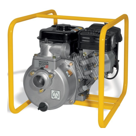
- Page 1 0163172en 0806 Pump PG 2 PG 2A PG 3 PG 3A REPAIR MANUAL...
- Page 3 PG Repair Foreword This manual covers machines with Item Number: 0007658, 0007659, 0009054, 0009055, 0009496, 0009498 Operating / Parts Information You must be familiar with the operation of this machine before you attempt to troubleshoot or repair it. Basic operating and maintenance procedures are described in the Operator’s Manual supplied with the machine.
- Page 4 Foreword PG Repair CALIFORNIA Proposition 65 Warning: Engine exhaust, some of its constituents, and certain vehicle components, contain or emit chemicals known to the State of WARNING California to cause cancer and birth defects or other reproductive harm. Laws Pertaining to Spark Arresters Notice: State Health Safety Codes and Public Resources Codes specify that in certain locations spark arresters be used on internal combustion engines that use hydrocarbon fuels.
-
Page 5: Table Of Contents
Label Locations ..................7 Safety Labels ..................8 Technical Data Technical Data—PG 2 Machines with Honda Engines ...... 10 Sound Specifications—PG 2 Machines with Honda Engines ..... 11 Dimensions—PG 2 Machines with Honda Engines ......11 Technical Data—PG 3 Machines with Honda Engines ...... 12 Sound Specifications—PG 3 Machines with Honda Engines ..... - Page 6 Table of Contents PG 2A Spark Plug ...................25 Air Cleaner—Machines with Honda Engines ........26 Air Cleaner—Machines with Wacker Engines ........27 Engine Oil—Machines with Honda Engines ........28 Cleaning Sediment Cup—Machines with Honda Engines ....28 4.10 Changing Engine Oil—Machines with Wacker Engines ......29 4.11 Cleaning Fuel Strainer—Machines with Wacker Engines ....29 4.12...
-
Page 7: Safety Information
PG Pumps Safety Information Safety Information This manual contains DANGER, WARNING, CAUTION, NOTICE and NOTE callouts which must be followed to reduce the possibility of personal injury, damage to the equipment, or improper service. This is the safety alert symbol. It is used to alert you to potential personal injury hazards. -
Page 8: Operating Safety
Safety Information PG Pumps Operating Safety Familiarity and proper training are required for the safe operation of equipment. Equipment operated improperly or by untrained personnel can be dangerous. Read the operating instructions contained in both WARNING this manual and the engine manual and familiarize yourself with the location and proper use of all controls. -
Page 9: Operator Safety While Using Internal Combustion Engines
PG Pumps Safety Information 1.1.14 ALWAYS be sure the machine is on a firm, level surface and will not tip, roll, slide, or fall while operating. 1.1.15 ALWAYS close fuel valve on engines equipped with one when machine is not being operated. 1.1.16 ALWAYS store the equipment properly when it is not being used. -
Page 10: Service Safety
Safety Information PG Pumps Service Safety Poorly maintained equipment can become a safety hazard! In order for the equipment to operate safely and properly over a long period of time, periodic maintenance and occasional repairs are necessary. WARNING 1.3.1 DO NOT attempt to clean or service the machine while it is running. Rotating parts can cause severe injury. -
Page 11: Label Locations
PG Pumps Safety Information Label Locations w c _ g r 0 0 0 8 3 3 wc_si000180gb.fm... -
Page 12: Safety Labels
Safety Information PG Pumps Safety Labels Wacker machines use international pictorial labels where needed. These labels are described below: Label Meaning DANGER! Engines emit carbon monoxide; operate only in well-ventilated area. Read the Operator’s Manual. No sparks, flames, or burning objects near the machine. - Page 13 PG Pumps Safety Information Label Meaning A nameplate listing the model number, item number, revision number, and serial number is attached to each unit. Please record the information found on this plate so it will be available should the nameplate become lost or damaged.
-
Page 14: Technical Data
Technical Data PG Pumps Technical Data Technical Data—PG 2 Machines with Honda Engines Item Number: PG 2A PG 2A 0009054 0009054 Rev. 102 and lower, Rev. 103 and higher 0007658 Engine Engine Make Honda Engine Model GX120K1WKT2 GX120K1WKT4 Rated Power kW (Hp) 3.0 (4.0) -
Page 15: Sound Specifications-Pg 2 Machines With Honda Engines
PG Pumps Technical Data Sound Specifications—PG 2 Machines with Honda Engines The required sound specification, Paragraph 1.7.4.f of 89/392/EEC Machinery Directive, is: - the sound pressure level at operator’s location (L ) = 84 dB(A) - the guaranteed sound power level (L... -
Page 16: Technical Data-Pg 3 Machines With Honda Engines
Technical Data PG Pumps Technical Data—PG 3 Machines with Honda Engines Item Number: PG 3A PG 3A 0009055 Rev. 102 0009055 Rev. 103 and lower, and higher 0007659 Engine Engine Make Honda Engine Model GX160K1WKT2 GX160K1WKT4 Rated Power kW (Hp) 4.1 (5.5) Spark Plug NGK BPR 6ES... -
Page 17: Sound Specifications-Pg 3 Machines With Honda Engines
PG Pumps Technical Data Sound Specifications—PG 3 Machines with Honda Engines The required sound specification, Paragraph 1.7.4.f of 89/392/EEC Machinery Directive, is: - the sound pressure level at operator’s location (L ) = 87 dB(A) - the sound power level (L ) = 108 dB(A) These sound values were determined according to ISO 3744 for the sound power level (L... -
Page 18: Technical Data-Machines With Wacker Engines
Technical Data PG Pumps Technical Data—Machines with Wacker Engines Item Number: PG 2 PG 3 0009496, 0009497 0009498, 0009499 Engine Engine Make Wacker Engine Model WM 130 WM 170 Displacement 126 (7.7) 169 (10.3) Engine Speed 3600 ± 100 Max. Operating Power kW (Hp) 3.2 (4.3) -
Page 19: Pump-Machines With Wacker Engines
The required sound specification, Paragraph 1.7.4.f of 89/392/EEC Machinery Directive, is: • the sound pressure level at operator's location (L PG 2 = 84 dB(A), PG 3 = 87 dB(A). • the guaranteed sound power level (L PG 2 = 103 dB(A), PG 3 = 105 dB(A). -
Page 20: Operation
Operation PG Pumps Operation Application This pump is intended for removing clean water and water containing some debris and solids. Refer to “Technical Data” for maximum solid size. Recommended Fuel The engine requires regular grade unleaded gasoline. Use only fresh, clean gasoline. -
Page 21: Before Starting
PG Pumps Operation Before Starting See Graphic: wc_gr000835 3.3.1 Read safety instructions at the beginning of manual. 3.3.2 Place pump as near to water as possible, on a firm, flat, level surface. 3.3.3 To prime pump, remove prime plug (a) and fill pump case with water. If the pump case is not filled with water before starting, it will not begin pumping. -
Page 22: To Start-Machines With Honda Engines
Operation PG Pumps To Start—Machines with Honda Engines See Graphic: wc_gr000014 3.4.1 Open fuel valve by moving lever to the right (a1). Note: If engine is cold, move choke lever to close position (b1) . If engine is hot, set choke to open position (b2) . 3.4.2 Turn engine switch to “ON”... -
Page 23: To Start-Machines With Wacker Engines
PG Pumps Operation To Start—Machines with Wacker Engines See Graphic: wc_gr000655 3.6.1 Open fuel valve by moving lever down (a1). Note: If engine is cold, move choke lever to close position (d2) . If engine is hot, set choke to open position (d1) . 3.6.2 Turn engine switch to “ON”... -
Page 24: Operation
Operation PG Pumps Operation Pump should begin pumping water within a minute depending on length of suction hose and height of pump above water. Longer hoses will require more time. If pump does not prime, check for loose fittings or air leak in suction hose. -
Page 25: Maintenance
PG Pumps Maintenance Maintenance Periodic Maintenance Schedule Daily After Every Every Every before first starting 20 hrs. hrs. hrs. hrs. Check fuel level. Check engine oil level. Inspect air filter. Replace as needed. Check external hardware. Inspect hoses and housing for leaks. Clean air cleaner element. -
Page 26: Cleaning Pump
Maintenance PG Pumps Cleaning Pump See Graphic: wc_gr000837 After pumping water containing a large amount of dirt or debris, clean out inside of pump housing. 4.2.1 Remove drain plug (b) from pump housing and drain any water left in pump. 4.2.2 Loosen the four knobs holding the pump cover (a) and remove cover. -
Page 27: Adjusting Impeller Clearance
PG Pumps Maintenance Adjusting Impeller Clearance See Graphic: wc_gr000838 If it is necessary to replace impeller or volute, be sure clearance between impeller and volute is adjusted correctly. The impeller (a) should be as close to the volute (b) as possible without rubbing against it. -
Page 28: Mechanical Seal Replacement
Maintenance PG Pumps Mechanical Seal Replacement See Graphic: wc_gr000839 To service the mechanical seal do the following: 4.4.1 Remove the impeller (a) from the engine shaft by turning it countercockwise. Note: If the impeller is hard to remove, tap it with a plastic mallet. Do not lose any adjusting shims (b) . -
Page 29: Spark Plug
PG Pumps Maintenance Spark Plug See Graphic: wc_gr000028 Clean or replace spark plug as needed to ensure proper operation. The muffler becomes very hot during operation and remains hot for a while after stopping the engine. Do not touch the muffler while it is hot. WARNING Note: Refer to the Technical Data for the recommended spark plug type and the electrode gap setting. -
Page 30: Air Cleaner-Machines With Honda Engines
Maintenance PG Pumps Air Cleaner—Machines with Honda Engines See Graphic: wc_gr000840 Service air cleaner frequently to prevent carburetor malfunction. NOTICE : NEVER run engine without air cleaner. Severe engine damage will occur. NEVER use gasoline or other types of low flash point solvents for cleaning the air cleaner. -
Page 31: Air Cleaner-Machines With Wacker Engines
PG Pumps Maintenance Air Cleaner—Machines with Wacker Engines See Graphic: wc_gr000656 NEVER use gasoline or other types of low flash point solvents for cleaning the air cleaner. A fire or explosion could result. WARNING NOTICE : NEVER run engine without air cleaner. Severe engine damage will occur. -
Page 32: Engine Oil-Machines With Honda Engines
Maintenance PG Pumps Engine Oil—Machines with Honda Engines See Graphic: wc_gr000022 4.8.1 Drain the oil while the engine is still warm. 4.8.2 Remove the oil filler plug (a) and the drain plug (b) to drain the oil. Note: In the interests of environmental protection, place a plastic sheet and a container under the machine to collect any liquid that drains off. -
Page 33: Changing Engine Oil-Machines With Wacker Engines
PG Pumps Maintenance 4.10 Changing Engine Oil—Machines with Wacker Engines See Graphic: wc_gr000087 4.10.1 Drain oil while engine is still warm. Note: In the interests of environmental protection, place a plastic sheet and a container under the machine to collect any liquid which drains off. -
Page 34: Carburetor Adjustment-Machines With Honda Engines
Maintenance PG Pumps 4.12 Carburetor Adjustment—Machines with Honda Engines See Graphic: wc_gr000032 4.12.1 Start the engine and allow it to warm up to operating temperature. 4.12.2 Set the pilot screw (a) two turns out. See Note . 4.12.3 With the engine idling, turn the pilot screw (a) in or out to the setting that produces the highest rpm. -
Page 35: Storage
PG Pumps Maintenance 4.14 Storage If pump is being stored for more than 30 days: NEVER open priming plug, discharge plug, or cover when pump is hot. WARNING 4.14.1 Remove discharge plug from pump casing and drain out any water left in the housing after pump has cooled. -
Page 36: Troubleshooting
Maintenance PG Pumps 4.15 Troubleshooting Problem / Symptom Reason / Remedy Pump does not take in water. • Not enough priming water in housing. • Engine speed too low. Adjust speed. • Strainer plugged. Clean strainer. • Suction hose damaged. Replace or repair hose. •... -
Page 37: Disassembly/Assembly Procedures
PG Repair Disassembly/Assembly Procedures Disassembly/Assembly Procedures Tools Because all possible problems encountered while repairing the machine cannot be anticipated, it is up to the mechanic to use common sense and good judgement in tool selection. The use of any special tools is recommended only for those operations where the use of conventional tools proves inadequate. -
Page 38: Description And Operation
Disassembly/Assembly Procedures PG Repair Description and Operation See Graphic: wc_gr003495 PG Series Pumps use an impeller (1) and volute (2) to create the suction and discharge pressures required for pump operation. The impeller is threaded directly to the engine drive shaft (3) and rotates inside the volute casing. - Page 39 PG Repair Disassembly/Assembly Procedures wc_gr003495 wc_tx000608gb.fm...
-
Page 40: Inspection
Disassembly/Assembly Procedures PG Repair Inspection Before disassembling the pump, check for conditions both outside and inside the pump which could affect performance. Inspecting conditions outside the pump: • Check that the pump is operating within specifications Remember that as suction lift and discharge head increases, pump output is reduced. - Page 41 PG Repair Disassembly/Assembly Procedures • Check the flapper valve and inlet port for leaks or damage. If the flapper valve is worn or distorted, it may not seal tightly. Inspect the threads on the inlet port nipple for deep scratches which could allow air leaks.
-
Page 42: Pump Exploded View
Disassembly/Assembly Procedures PG Repair Pump Exploded View wc_gr003496 wc_tx000608gb.fm... -
Page 43: Pump Components
PG Repair Disassembly/Assembly Procedures Pump Components Ref. Description Ref. Description Plug Ring O-ring Volute Screw Impeller Discharge port O-ring Discharge gasket Mounting flange Screw Washer Suction port Mechanical seal Flapper valve gasket Screw Screw Washer Pump case housing wc_tx000608gb.fm... -
Page 44: Replacing The Flapper Valve
Disassembly/Assembly Procedures PG Repair Replacing the Flapper Valve See Graphic: wc_gr003497 The flapper valve (1) is located at the pump inlet (2). During operation, this valve is open allowing a free path for water to flow into the pump case. When the pump is stopped, it closes and prevents water in the suction line from being lost. -
Page 45: Frame Assembly
PG Repair Disassembly/Assembly Procedures Frame Assembly See Graphic: wc_gr003498 Removal: 5.9.1 Remove the four screws (1) and nuts (2) the secure the pump/engine (3) to the frame (4). Installation: 5.9.2 Secure the pump/engine (3) to the frame (4) using screws (1) and nuts (2). -
Page 46: Pump Housing
Disassembly/Assembly Procedures PG Repair 5.10 Pump Housing See Graphic: wc_gr003499 Removal: 5.10.1 Remove the drain plug (5) from the bottom of the pump housing and drain the water from the pump housing. 5.10.2 Remove the four screws (6) securing the pump housing (7) to the back pump flange (8). - Page 47 PG Repair Disassembly/Assembly Procedures wc_gr003499 wc_tx000608gb.fm...
-
Page 48: Impeller
Disassembly/Assembly Procedures PG Repair 5.11 Impeller See Graphic: wc_gr003500 CAUTION: When replacing either the impeller (1) or the rear pump flange (2), make note of the I.D. numbers found on back of each component casting (3). MAKE SURE THE REPLACEMENT PARTS HAVE THE SAME NUMBER MARKINGS—THE PARTS ARE NOT INTERCHANGEABLE. - Page 49 PG Repair Disassembly/Assembly Procedures E-50 PE-50 wc_gr003500 wc_tx000608gb.fm...
-
Page 50: Replacing The Mechanical Seal
Disassembly/Assembly Procedures PG Repair 5.12 Replacing the Mechanical Seal See Graphic: wc_gr003500 Removal: 5.12.1 Remove the impeller (1). See section Impeller . Note: Do not lose any adjusting shims (7). 5.12.2 Remove the mechanical seal spring (8) and the carbon face (9) from the engine shaft. - Page 51 PG Repair Disassembly/Assembly Procedures E-50 PE-50 wc_gr003500 wc_tx000608gb.fm...
-
Page 52: Testing
Disassembly/Assembly Procedures PG Repair 5.13 Testing See Graphic: wc_gr003501 This procedure requires a vacuum gauge (P/N 28755) and a tachometer. 5.13.1 Fill the pump housing with cold water until it flows out from the discharge port. 5.13.2 Tighten the pump cover and the prime plug. 5.13.3 Bring the engine up to operating speed. - Page 53 PG Repair Disassembly/Assembly Procedures wc_gr003501 wc_tx000608gb.fm...
- Page 54 Disassembly/Assembly Procedures PG Repair wc_tx000608gb.fm...
- Page 55 Threadlockers and Sealants Threadlockers and Sealants Threadlocking adhesives and sealants are specified throughout this manual by a notation of “S” plus a number (S#) and should be used where indicated. Threadlocking compounds normally break down at temperatures above 175°C (350°F). If a screw or bolt is hard to remove, heat it using a small propane torch to break down the sealant.
- Page 56 Threadlockers and Sealants Threadlockers and Sealants (continued) Threadlocking adhesives and sealants are specified throughout this manual by a notation of “S” plus a number (S#) and should be used where indicated. Threadlocking compounds normally break down at temperatures above 175°C (350°F). If a screw or bolt is hard to remove, heat it using a small propane torch to break down the sealant.
- Page 57 Torque Values Torque Values Metric Fasteners (DIN) TORQUE VALUES (Based on Bolt Size and Hardness) WRENCH SIZE 10.9 12.9 Size ft.lb. ft.lb. ft.lb. Metric Inch Metric Inch 7/32 – 9/32 – 5/16 – – – – 11/16 – – – 15/16 –...
- Page 58 Torque Values Torque Values (continued) Inch Fasteners (SAE) Size ft.lb. ft.lb. ft.lb. Metric Inch Metric Inch No.4 – 3/32 No.6 5/16 – 7/64 No.8 11/32 – 9/64 No.10 – – 5/32 – 7/16 – 3/32 5/16 – – 9/16 – 5/16 7/16 –...
- Page 60 Wacker Construction Equipment AG · Preußenstraße 41 · D-80809 München · Tel.: +49-(0)89-3 54 02 - 0 · Fax: +49 - (0)89-3 54 02-3 90 Wacker Corporation · P.O. Box 9007 · Menomonee Falls, WI 53052-9007 · Tel. : (262) 255-0500 · Fax: (262) 255-0550 · Tel. : (800) 770-0957 Wacker Asia Pacific Operations ·...
Need help?
Do you have a question about the PG 2 and is the answer not in the manual?
Questions and answers