Eaton VCP-W Manual
Electrical ground and test device (complex)
Hide thumbs
Also See for VCP-W:
- Instructions for installation, operation and maintenance (81 pages) ,
- Operation (12 pages) ,
- Manual (5 pages)
Table of Contents
Advertisement
Quick Links
Cutler-Hammer
Type VCP-W Electrical Ground and Test Device (Complex)
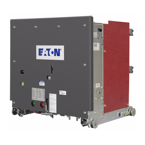
Figure 1 Type VCP-W Electrical Ground and Test
Device
TABLE OF CONTENTS
1-1
Purpose . . . . . . . . . . . . . . . . . . . . . . . . . . . . . .1
1-2
Description . . . . . . . . . . . . . . . . . . . . . . . . . . . .1
1-2.1
Power Grounding Switch Operation . . . . . . . .2
1-2.2
Terminal Selector Switch Operation . . . . . . . .2
1-3
Interlocks and Safety Features . . . . . . . . . . . .2
1-4
Operation . . . . . . . . . . . . . . . . . . . . . . . . . . . . .4
1-4.1
Safe Practices . . . . . . . . . . . . . . . . . . . . . . . . .4
1-4.2
Grounding . . . . . . . . . . . . . . . . . . . . . . . . . . . .4
1-4.3
Cable Testing . . . . . . . . . . . . . . . . . . . . . . . . .4
1-4.4
Phasing Out . . . . . . . . . . . . . . . . . . . . . . . . . . .5
Effective 11/97 Supersedes I.L. 3778A20A dated March, 1993
!
READ AND UNDERSTAND THESE INSTRUCTIONS
BEFORE ATTEMPTING TO USE THIS DEVICE.
IMPROPER USE CAN RESULT IN DEATH, BODILY
INJURY AND/OR PROPERTY DAMAGE.
!
BECAUSE OF THE UNIQUE APPLICATION AND
VAST VARIETY OF SYSTEM AND USER REQUIRE-
MENTS, SPECIFIC OPERATING PROCEDURES
MUST BE DEVELOPED BY THE USER. FAILURE TO
DEVELOP THESE PROCEDURES COULD LEAD TO
IMPROPER USE OR OTHER MORE SERIOUS CON-
SEQUENCES.
1-1 PURPOSE
The VCP-W Electrical Ground and Test Device is
designed for insertion into a Vac Clad-W switchgear
compartment to provide a safe and convenient means to
(Figure 1):
1. Ground the circuit for maintenance work,
2. Apply potential for cable testing,
3. Provide access to both bus and line circuits for
"Phasing out" tests.
1-2 DESCRIPTION
Vac Clad-W switchgear is a two-high arrangement. In
the lower compartment the top terminals normally con-
nect to the main bus and the bottom terminals normally
connect to the incoming line or feeders.
compartment the opposite normally holds true, i.e. the
top terminals connect to the incoming line or feeders
and the bottom terminals connect to the main bus. This
must be verified for each application. Because of this
two- high arrangement, the bus and line positions of the
Electrical Ground and Test Device terminals and test
ports will vary depending upon whether the device is
used in an upper or lower compartment. Therefore, on
the VCP-W Electrical Ground and Test Device the termi-
nals and selector switch positions are referred to as
"UPPER TERMINALS" and "LOWER TERMINALS"
only. The test ports are labeled "UPPER TERMINALS"
and "SELECTABLE TERMINALS", Figure 2.
I.L. 3778A20B
WARNING
CAUTION
In an upper
Advertisement
Table of Contents

Related Manuals for Eaton VCP-W


Summary of Contents for Eaton VCP-W
-
Page 1: Table Of Contents
Therefore, on the VCP-W Electrical Ground and Test Device the termi- nals and selector switch positions are referred to as “UPPER TERMINALS” and “LOWER TERMINALS”... -
Page 2: 1-2.1 Power Grounding Switch Operation
Figure 5. In order to change position The stored energy closing mechanism for the power of the selector switch: grounding switch is the same as used in type VCP-W breakers. It is capable of applying the ground against a 1. Insert the handle, “live”... - Page 3 I.L. 3778A20B Page 3 ing screw unless the grounding switch is tripped • The selector switch mechanism has a spring first. loaded latch pin which holds the blades latched either to the upper or lower terminals. • The device cannot be placed into the breaker compartment with the selector switch operating •...
-
Page 4: Operation
I.L. 3778A20B Page 4 1-4 OPERATION 1-4.2 GROUNDING 1-4.1 SAFE PRACTICES 1. With the device out of the breaker compartment, insert the selector switch operating handle and set the switch for upper or lower terminals as WARNING desired. Remove the handle. A GROUND AND TEST DEVICE IS A SAFETY- CAUTION RELATED DEVICE. -
Page 5: 1-4.4 Phasing Out
I.L. 3778A20B Page 5 CAUTION CAUTION DO NOT ATTEMPT TO OPERATE THE SELECTOR DO NOT ATTEMPT TO OPERATE THE SELECTOR SWITCH WHEN IT IS ON THE EXTENSION RAILS. SWITCH WHEN IT IS ON THE EXTENSION RAILS. FAILURE TO COMPLY COULD RESULT IN THE FAILURE TO COMPLY COULD RESULT IN THE DEVICE COMING OFF THE RAILS CAUSING BODILY DEVICE COMING OFF THE RAILS CAUSING BODILY... - Page 6 I.L. 3778A20B Page 6 34.81 3000A 3.88 12.00 13.63 34.69 1200 / 2000 A ➀ ➅ KT2 - Upper terminal test KT1 - Key interlock with auxiliary switch ➆ ports key interlock Selector switch blade ➁ ➇ Selectable terminal test ports padlock Upper terminals ➂...
- Page 7 I.L. 3778A20B Page 7 29.00 29.50 27.81 29.56 ➀ ➉ Upper terminal port Remote control receptacle ➁ KT2 - Upper terminal test Ground contact ports key interlock Control switch ➂ Selector switch position indicator Manual trip button ➃ Selectable terminal port Floor tripper ➄...
- Page 8 I.L. 3778A20B Page 8 ➀ ➃ KT1 - Interlock key Selector switch interlock plates · ➄ Removable only when selector switch Selector switch position latch pin ➅ locked with lower terminals Selector switch operating lever · With key removed, grounding (switch engaged with lower terminals) ➆...
- Page 9 I.L. 3778A20B Page 9 ➀ ➂ Selector switch operating handle engaged Spring loaded latch pin operating ring (switch connected with lower terminals) ➁ ➃ Spring loaded latch pin Handle position showing selector switch · Pull to engage selector switch handle engaged with upper terminals ·...
- Page 10 I.L. 3778A20B Page 10 Control Switch Box with 50 ft. # 14-3 Cable and 3 Prong Male Twist Lock Connector Ground and Test Device has 3 Hole Female Socket WHITE CLOSE OPEN GREEN CS = Control Switch: Vertical : No Circuit (Spring Return Position) CW : Close CCW : Trip Y = Anti Pump Relay...
- Page 11 I.L. 3778A20B Page 11 Control Switch Box with 50 ft. # 14-3 Cable and 3 Prong Male Twist Lock Connector Ground and Test Device has 3 Hole Female Socket WHITE CLOSE BLACK CS = Control Switch: CCW __Charge & Close Vertical : No Circuit (Spring Return Position) Y = Seal in Relay M = Charging Motor...
- Page 12 I.L. 3778A20B Page 12 Cutler-Hammer Five Parkway Center Pittsburgh, PA 15220 Effective 11/97 (ISI) Style 3778A20B Printed in U.S.A.
Need help?
Do you have a question about the VCP-W and is the answer not in the manual?
Questions and answers