
Subscribe to Our Youtube Channel
Related Manuals for phytron MSX MINI


Summary of Contents for phytron MSX MINI
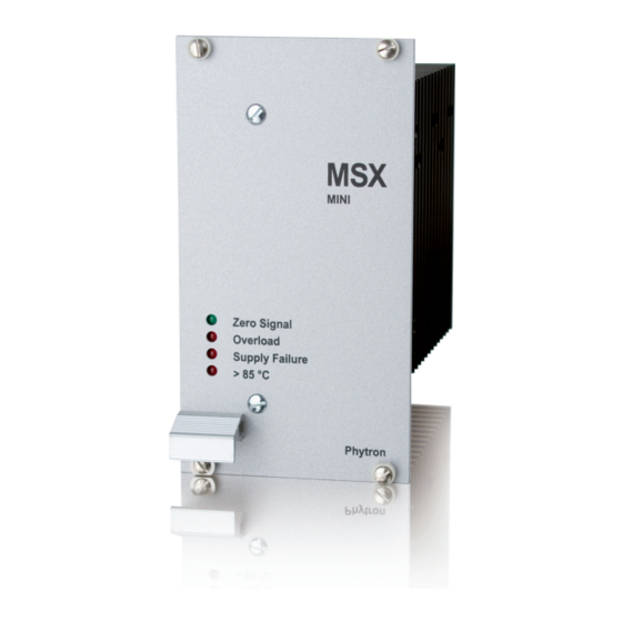
- Page 1 MINI Ministep Power Stage for Bipolare Control Mode MANUAL 2107-A005 EN Extreme. Precision. Positioning.
- Page 2 MSX 152-120 MINI Stepper Motor Power Stages for Bipolar Control Mode 03/2018 Manual MA 2107-A005 EN...
- Page 3 / or the devices described herein without prior notification. We appreciate suggestions and criticisms for further improvement. Please send your comments to the following e-mail address: doku@phytron.de You’ll find the updated version of this manual on the website of www.phytron.de. MA 2107-A005 EN...
-
Page 4: Table Of Contents
Contents 1 MSX MINI ........... 4 8 Inputs ............30 1.1 Short Overview ........4 8.1 MSX 5 V Standard and MSX 5 V RESET Inputs 30 1.2 Extent of Supply ........7 8.2 MSX 24 V Input ........30 1.3 Pin assignment ........ -
Page 5: Msx Mini
Ministep power stages for two-phase stepper motors The power stages type MSX are used for bipolar control of two-phase stepper motors with phytron’s welltried technology, now with enhanced 4 quadrant chopper type current control. Run and stop current can be set by rotary switches. Overdrive, Boost, Activation and Motor direction are activated by DIP switches. - Page 6 Fig. 2: Front view without panel Motor currents from 4.4 to 15.4 A Peak Run and stop current can be individually set by rotary switches. The MSX automatically changes to the stop current, if there aren’t any control pulse signals. The Boost current (130 % of the preset run current) can either be activated by the input Boost or is permanently switched on by DIP switch.
- Page 7 Manual MSX MINI Inputs The inputs of the power stages MSX can be controlled with 5 V or 24 V input level via optocouplers. The inputs Control pulse , Motor direction, Boost and Activation are designed for Open- Collector controlling. The inputs are optically insulated from the MSX power supply voltage.
-
Page 8: Extent Of Supply
1.2 Extent of Supply The MSX is available in the following options: Type MSX 120V Version ID-No. MSX 152 (5 V) Standard, #10004904 replacement for MSO and MINI MSX 152 (24 V) Replacement for SMD #10008753 MSX 152 (5 V-RESET) -
Page 9: Pin Assignment
Manual MSX MINI 1.3 Pin assignment Fig. 3: 32-pin male multipoint connector acc. to DIN 41612, version D Important: The output currents must not exceed 10 A during continuous operation to avoid r.m.s overheating of the connector. Therefore, the BOOST function for phase current increase by 30% must not permanently used in MSX 152 with maximum current. -
Page 10: Rotary Switches
1.4 Rotary Switches Run and stop current, step resolution and current shaping can be set by the three setting switches behind the front panel. Fig. 4: 16-stepped rotary switch: setting 0...F 1.5 DIP Switches Overdrive, Boost, Activation and Motor direction can be set by the four DIP switches behind the front panel. -
Page 11: Leds
Manual MSX MINI 1.6 LEDs shines Meaning Basic position green The signal Basic position is generated. (Zero Signal) Every 8 pulses in the half step mode etc. Overload Overload error in the MSX: A short-circuit over or between the motor phases or towards GND or +U has occured. -
Page 12: Block Diagram
1.7 Block Diagram Fig. 6: MSX block diagram MA 2107-A005 EN... -
Page 13: Technical Data Table
Manual MSX MINI 2 Technical Data Table Technical Data Two-phase stepper motors with 4, 6 or 8-lead wiring scheme Stepper motor Winding resistance < 10 Ohm Winding inductance should be higher than 0.5 mH per phase Step resolution and Step resolution and Current shape are set by rotary switch: Current shape Step resolution: 1/1, 1/2, 1/4, 1/5, 1/10, 1/20 of a full step with or without torque... - Page 14 Technical Data Inputs All inputs include an optocoupler with series resistors for 5 V or 24 V-supply voltage. The signals are active, when the optocoupler is energized. Optocoupler input current is about 10 mA for MSX 5 V standard version or...
- Page 15 Manual MSX MINI Technical Data Error Supply voltage < 40 V or > 160 V Overtemperature (T > 85° C) Overcurrent, short circuit The power stage is deactivated in case of an error message. Cooling Fan with 50 m /h air flow Ambient Operation: 4 to +40 °C *)
-
Page 16: To Consider Before Installation
3 To Consider Before Installation Read this manual very carefully before installing and operating the MSX. Observe the safety instructions in the following chapter! 3.1 Qualified Personnel Design, installation and operation of systems using the MSX may only be performed by qualified and trained personnel. -
Page 17: Protective Measure For Power Stage Operation
Manual MSX MINI 3.3 Protective Measure for Power Stage Operation The MSX must be operated according to VDE 0100 part 200 with protection by automatic disconnection. Therefore, the motor, power stage, `0 V` and each equipment has to be grounded. When protection by automatic disconnection (EN 61140, VDE 0100, part 410) is used for power stages with definite voltage >... -
Page 18: Putting Into Service
3.4 Putting into Service • Check the output voltage of the supply unit before plugging in the MSX unit. • Never plug or unplug the unit when powered. • Excessive heating of the motor is probably caused by setting too high motor current. -
Page 19: Dimensions
Manual MSX MINI 4 Dimensions Fig. 7: Dimensions MA 2107-A005 EN... -
Page 20: Mains Supply Unit
5 Mains Supply Unit The MSX power stage can be supplied by means of an unregulated filtered DC voltage from 60 to 120 V Admissible voltage range: 40 to 160 V The voltage must not drop under 40 V or rise over 160 V, not even for a short time (>... - Page 21 Manual MSX MINI For calculation and connection of the supply unit, the following instructions should be followed: The transformer must be constructed with reinforced or double insulation. The calculation of the fuse F2 depends on the preset phase current and the motor load: Withstand voltage >= 200 V Recommended values: T10 A...
-
Page 22: Calculation And Connection
5.1 Calculation and Connection For calculation and connection of the supply unit, the following instructions should be followed: 1. All mating connector terminals indicated in the connecting diagram must be connected to the cable. Example: + U must be connected to the pins 12a, 12c, 14a and 14c. -
Page 23: Insulation Overview
Manual MSX MINI 6. SB 234 damping module: The operating voltage range of the power stage is wide enough compared to the nominal voltage. Even in case of high voltage variations or voltage drops (motor feeds energy back and the load capacitor voltage increases), no error signal SUPPLY FAILURE should be generated. -
Page 24: Motor Connection
6 Motor Connection The following chapter describes how to wire different types of Two-phase stepper motors. MSX stepper motor power stages may be connected to stepper motors with 1.1 to 15.4 A phase current. Peak The stepper motor winding resistance should be less than 10 Ohm for full power. -
Page 25: Shielding
Manual MSX MINI 6.1 Shielding To avoid disturbances affecting the wires and instruments installed close to the drive system, we recommend to use shielded cables. The power supply unit in which the MSX is built-in and the motor should be connected to ground by a central earthing tab. -
Page 26: Wiring Schemes
6.2 Wiring Schemes Fig. 11: Connection diagrams for 4-, 6- and 8-wire stepper motors MA 2107-A005 EN... -
Page 27: Motor Cable
Manual MSX MINI 6.3 Motor Cable We recommend to wire the stepper motor with a 5-lead cable with shielding mesh. For optimum electromagnetic compatibility (EMC), the cable should not be interrupted by additional connectors or screw terminals. The protective earth wire (green/yellow) of the motor cable should be connected to the earthing screw near the motor connector of the MSX plug-in power stage unit. -
Page 28: Rotary Switches And Dip Switches
7 Rotary Switches and DIP Switches Run and stop current can be individually set by both rotary switches. Besides, Step resolution and Current shape can be selected by the third one. Run and stop current is increased by 30 % with Boost. -
Page 29: Motor Current Rotary Switches
Manual MSX MINI 7.1 Motor Current Rotary Switches Run and Stop current rotary switches Switch Phase current position in A r.m.s. Factory settings • The stop current is normally set to 40-50% of the run current, to keep the motor temperature as low as possible. -
Page 30: Step Resolution And Current Shape Rotary Switch
7.2 Step Resolution and Current Shape Rotary Switch The rotary switch below the DIP switches is used to set the phase current profile. Step resolution and Current Shape Rotary switch Switch position Current Shape Full step Half step with DMA... -
Page 31: Inputs
Manual MSX MINI 8 Inputs The control inputs Control pulse , Motor direction, Boost , Activation and Reset are electrically insulated by optocoupler from the MSX supply voltage (+U ). This assures best noise suppression between control and power circuit. The signals are active, when current flows through the optocoupler. -
Page 32: Control Pulse Input
Input Control pulse Maximum step frequency: 500 kHz Minimum pulse width: 1 µs A negative control pulse of 1 µs causes a motor step. The step is done with the falling flank of the control pulse and the current is changed from run to stop current. If the time between two control pulses is more than 40 ms, the stop current is activated. -
Page 33: Boost Input
Manual MSX MINI Input Boost If the input optocoupler is energized the MSX changes Boost current. The power stage increases the run and stop current by 30%. Thus, a higher torque can be reached during the acceleration and deceleration time of the motor by changing to boost current. - Page 34 Jumper position Jumper position Reset: Activation: Fig. 15: Board with J1 jumper The power stage is set to a defined initial state with Reset =0 (low active), that means that all error messages and the ring counter are reset. Then, the ring counter is in basic position.
-
Page 35: Outputs
Manual MSX MINI 9 Outputs Open-Collector-Darlington outputs insulated by means of optocoupler = 20 mA, U = 45 V, UCE at 20 mA < 0.6 V Fig. 17: Output wiring diagram If inductive loads (e. g. a relay, motor brake) are connected, a protective diode must be mounted. -
Page 36: Error Output
9.2 Error Output The Error output is active high to detect power failure and cable break. This output is active, when the following limits are exceeded or are fallen below. Simultaneously, the motor is deactivated: Limits Error message Motor current >... -
Page 37: Appendix A: Technical Details
Manual MSX MINI Appendix A: Technical Details A stepper motor can be used with different step resolutions, which are described in the first part of this chapter. The functions Boost, Overdrive, Current Shaping CS and Current Optimization BLOW UP you’ll find in the second part. A1 FULL STEP / HALF STEP / MINISTEP FULL STEP The FULL STEP mode is the operating mode in which a 200-step motor, for example,... - Page 38 HALF STEP The motor step resolution can be electronically multiplied by 2 by alternately energizing the stepper motor’s phases 1, 1+2, 2 etc.. This is the HALF STEP mode. The torque, however, is reduced in the half step mode, compared to the full step mode.
- Page 39 Manual MSX MINI MINISTEP The MSX power stage increases the step resolution by a factor 2, 4, 5, 10 or 20 of a full step – MINISTEP MODE. Various advantages are obtained by the MINISTEP MODE • The torque undulation drops when the number of ministeps is increased. •...
-
Page 40: A2 Boost
A2 Boost The motor torque required during acceleration and deceleration is higher than that required during continuous motor operation (f ). For fast acceleration and deceleration settings, (steep ramps), the motor current is too high during continuous operation and results in motor overheating. -
Page 41: A3 Overdrive
Manual MSX MINI A3 Overdrive Overdrive is a dynamic boost function, which will be automatically switched on if this makes sense in regard of the current shape. Overdrive is activated by DIP switches. Fig. 22: Phase currents with Overdrive The Overdrive function increases the r.m.s. phase current automatically by a factor of for all frequencies >... - Page 42 The stepper motor phase current decreases with increasing step frequency caused by the counter-electromotive force of the motor. The overdrive function compensates the decrease of current and torque. The phase current is increased by about 40 %. The table...
- Page 43 Manual MSX MINI Fig. 23: Phase current diagram of one phase in with or without Overdrive in full step and 1/10- step mode Remark: The current shape in the Ministep mode with Overdrive is similar to that of the full step mode, however, in the 1/n-Ministep mode the number of pulses necessary to attain the same speed is n times higher than in the full step mode.
-
Page 44: A4 Current Shaping Cs
A4 Current Shaping CS Current Shaping (CS) is a circuitry method for delivering a true phase current which corresponds for a wide range of frequencies to a selected current shape (CS= 4 quadrant current regulation). If the stepper motor is driven without CS, the true current differs from the specified current, even in the lower speed frequencies. -
Page 45: A5 Optimization Of The Current Shape - Blow Up
Manual MSX MINI A5 Optimization of the Current Shape - BLOW UP For an ideal stepper motor the holding torque is a true sine wave. In practice, the torque curve more or less differs from this ideal shape. Therefore the MSX offers the possibility to select a current shape as shown in figure 24. In function of the motor used, it is possible to increase the motor performance during run and acceleration. -
Page 46: A6 Current Delay Time
A6 Current Delay Time After the last control pulse the stop current is activated after a waiting time. The waiting time after the last control pulse until change to stop current is called current delay time. We recommend tospecify t so that the motor’s oscillations are dying out after the last... -
Page 47: Appendix B: G-Msx Adaptor Board
Manual MSX MINI Appendix B: G-MSX Adaptor Board Type MSX power stages can be directly plugged on the G-MSX adaptor board. The adaptor board includes connectors for motor cable (ST4 to ST7), signal lines (ST2) and supply voltage (ST8 and ST9). The control signals for Open-Collector controlling are connected to the ST2. - Page 48 Jumper positions J1 Jumper position Open-Collector controlling SLS-A 1 – 2 Auxiliary voltage for IXEα 2 – 3 Basic position Fig. 29: ST2 10-pin connector Safety Instructions: • The G-MSX adaptor board must only be connected and put into service by qualified and trained personnel.
-
Page 49: C1 Warranty
In this chapter warranty and ESD protective measures are described. C1 Warranty The MSX power stages are subject to legal warranty. Phytron will repair or exchange devices which show a failure due to defects in material or caused by the production process. -
Page 50: Appendix D: Declarations Of Conformity
Appendix D: Declarations of Conformity MA 2107-A005 EN... - Page 51 Manual MSX MINI MA 2107-A005 EN...
-
Page 52: Index
Index Activation 13, 32 Lead cross section 14, 26 Adaptor board 46 Load capacitor 21 Ambient temperatures 14 Ministep 38 Basic position 13, 33 Motor cable 26 Blow up 44 Motor direction 13, 31 Boost 13, 32, 39 Motor time constant 23... - Page 53 Phytron GmbH Industriestraße 12 – 82194 Gröbenzell T+49-8142-503-0 F +49-8142-503-190 www.phytron.eu...
Need help?
Do you have a question about the MSX MINI and is the answer not in the manual?
Questions and answers