
Related Manuals for phytron IXEa-A Series


Summary of Contents for phytron IXEa-A Series
- Page 1 IXE –A User Manual for the Stepper Motor Control Unit Type IXE -A Manual 1206-A001 GB...
- Page 3 ® phytron User Manual for Stepper Motor Control Units IXEα–A Manual MA 1206-A001 GB...
- Page 4 User Manual IXEα−A © 2003 All rights with: Phytron-Elektronik GmbH Industriestraße 12 82194 Gröbenzell, Germany Tel.: +49 8142/503-0 Fax: +49 8142/503-190 Every possible care has been taken to ensure the accuracy of this technical manual. All information contained in this manual is correct to the best of our knowledge and belief but cannot be guaranteed.
-
Page 5: Table Of Contents
1.1 Short View ........................5 1.2 Basic Unit and Options of the IXEα-A Series ..............6 1.3 Dimensions........................7 1.4 PHYTRON Stepper Motor Power Stages..............8 1.5 Stepper Motor........................ 8 1.6 Safety Instructions......................9 1.7 Control and Programming Instructions................9 2 Keyboard Operation ...................... - Page 6 User Manual IXEα−A 2.9.1 Print Text in a Program..................22 2.10 Error Messages ...................... 22 2.10.1 Programming Errors ................... 22 2.10.2 Error Message From the Power Stage ............... 22 2.10.3 EMERGENCY STOP Error Message ..............23 3 Computer Mode......................... 23 3.1 Interface ........................
-
Page 7: Stepper Motor Control Units Ixeα-A
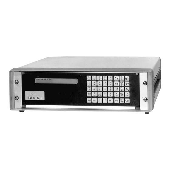
Short View Fig. 1: Stepper motor control unit IXEα-A with various options The IXEα-A are stepper motor control units by PHYTRON, with numerous applications in the industrial field and research laboratories. In the standard version, the control units type IXEα-A-RS are equipped with a RS232C computer interface. -
Page 8: Basic Unit And Options Of The Ixeα-A Series
IXEα-A-T display unit RS 232 C computer interface The basic unit for 1 to 8 axes with all types of PHYTRON power stages for 19“ racks. • 8 optocoupler isolated inputs • 8 outputs 24 V / 500 mA or 1.5 A power outputs •... -
Page 9: Dimensions
® phytron Dimensions Fig. 2: Dimensions for IXEα-A with power stages ZSO, ZSO MINI, MSO MINI, SYNCRO and SINCOS MA 1206-A001 GB... -
Page 10: Phytron Stepper Motor Power Stages
User Manual IXEα−A PHYTRON Stepper Motor Power Stages A great many applications are possible with the PHYTRON power stages of the ZSO, ZSO MINI, MSO MINI, SYNCRO and SINCOS series. Bipolar control in compact powerful module: Motor currents from 4 A... -
Page 11: Safety Instructions
® phytron Safety Instructions Read this manual and the device manual very carefully before installing and operating the controller. Observe the safety instructions in this and the following chapters. Design, putting into service and maintenance may only be performed by qualified and trained personnel. -
Page 12: Keyboard Operation
User Manual IXEα−A • Program names [name] in the instruction code can consist of up to 6 alphanumeric characters. • Before starting to edit the program, select the dialogue language (German/English/French). Adapt the data format and check the connections of the unit. All programmed parameters remain in memory even after switching the unit OFF. -
Page 13: Keyboard Assignment / Functions
® phytron Keyboard Assignment / Functions • After POWER ON, the lower characters and signs of the keys are activated. • Upper sign: press together with the corresponding key. • key: Change from capitals to normal characters All instructions, aside from certain exceptions, are introduced in capitals, for example : 'IS'. -
Page 14: Cursor Control Keys
User Manual IXEα−A 2.1.1 Cursor Control Keys These keys shift the cursor one character to the left or to the right These keys shift the cursor one line up (to line n-1) or down (to line n+1) Delete character Insert character Delete line Insert line Monitor Mode... -
Page 15: List Of Operation Modes
® phytron 2.2.1 List of Operation Modes The unit must be in the monitor mode. Then, type the code of the desired operating modes and confirm with Instruction Operating mode AP[name] Execute program [name] CP[name] Copy program [name] DP[name] Delete program [name]... -
Page 16: Manual Mode
User Manual IXEα−A Manual Mode In the Manual mode, all inputs are directly executed on the connected system. The Manual mode can be accessed from the Monitor mode. Instruction: H then confirm with Display: MANU X 12.34 mm = low run frequency f (f = high run frequency f' (f The engineering units for the displacement values are programmed in Parameter P02 (in our example: mm). -
Page 17: Frequency Switching F/F
® phytron 2.3.2 Frequency Switching f/f' key is used to modify the run frequency in the Manual mode: f (f ): press the f' (f ): press the keys The actual run frequency is displayed by = f' . 2.3.3 Input of Instructions in the Manual Mode It is possible to enter one or more instructions in the second line of the display unit when the unit is in the Manual mode. -
Page 18: Cancel An Instruction
User Manual IXEα−A 2.3.4 Cancel an Instruction makes the unit go back to the Manual mode. If one, or more instructions have been introduced on the second display line, they will not be executed. The cursor disappears. 2.3.5 Initialization / M0P If a mechanical zero is defined (reference point), absolute displacement instructions can be used. - Page 19 ® phytron Display: MANU X 1234.5678 mm Y 1234.5678 mm e1 Input 1 to 12 1001 0101 0000 In our example inputs 1,4,6,8 = ON and inputs 2,3,5,7,9,10,11,12 = OFF (deactivated) To display the next higher input group: press If no higher group is installed, the display goes back to the first group of inputs (e1).
-
Page 20: Programming
User Manual IXEα−A Programming Program instructions and commands are described in the Programming manual MINILOG. Some of these instructions only apply to the Computer mode or to the MINILOG programming language. The instructions are signed by – only computer mode. 2.4.1 Program Length The program length is variable, maximum length is 630 lines. -
Page 21: Non-Existing Program Line
® phytron 2.4.4 Non-existing Program Line If there is an attempt to call a non-existing program line in the program, the last existing line of the corresponding program is automatically displayed. 2.4.5 Insufficient Memory Space If the program memory RAM is insufficient to safeguard a program line, an error message will be displayed. -
Page 22: Program Start
User Manual IXEα−A Attention During the sequential program test, each axis is individually driven. In normal program run, the axis can cross if they are started in a same program line. This must be kept in mind during program testing to avoid any damage to the axes system due to collision. If an error is detected in the program, the test mode can be exited with (return to the Monitor mode). -
Page 23: Error Messages During Program Run
® phytron 2.6.1 Error Messages During Program Run Each error message interrupts the current program (refer to chapter 2.10 ). If the unit displays EMERGENCY STOP, this message must be confirmed by . The unit switches to the Monitor mode. Then, it is possible to initialize the axes in the Manual Mode (H). -
Page 24: Printer Operation
User Manual IXEα−A Printer Operation The program names, program lists, parameters or registers can be printed via the RS 232 interface. Important: The printer must be operated with a software-handshake, X-ON / X-OFF protocol (refer to the printer manual) The printer mode can be accessed when the IXEa-A-T is in the Monitor mode. Instructions: DSP[name] CR Print program [name] Print parameters... -
Page 25: Emergency Stop Error Message
® phytron Attention Repairs and maintenance inside the instruments must only be carried out by personnel familiar with safety regulations applying to electrical instruments ! 2.10.3 EMERGENCY STOP Error Message If the axis is displaced too far in the „+“ or „–„ directions, the limit switches are activated and EMERGENCY STOP (NOTHALT) is displayed. -
Page 26: Instruction Format For The Computer Mode
User Manual IXEα−A 3.1.1 Instruction Format for the Computer Mode All instruction strings should have the following format: STX „Instruction“ ETX CR LF The control characters are listed in the following ASCII code chart: BITS 0000 – 0001 “ 0010 0011 0100 0101... -
Page 27: General Remarks For The Computer Mode
RS232 IEEE488 Now, the control unit can only be controlled from the external computer. The communication program for PC from PHYTRON, α-COMM simplifies the control and programming of the units via external computer. In the Computer mode, there are 3 different ways of communicating between the computer and the control unit: 1. -
Page 28: Programming Instructions
User Manual IXEα−A The unit returns a combination of numbers which includes the information in decimal codes: Bit Decimal Signification value The control unit is not in the Computer mode The control unit is executing a program or an instruction External emergency stop Emergency stop of one axis Power stage error... -
Page 29: Power Stage Programming
® phytron 3.2.3 Power Stage Programming The power stages can be programmed by means of DIP switches (refer to the corresponding power stage manual). ACTIVATION The motor activation can also be programmed by means of an instruction. Refer to the Programming manual MINILOG. -
Page 30: Program And Data Maintaining
User Manual IXEα−A Program and Data Management Refer to Programming manual MINILOG. For control units without keyboard the program can be started by positioning the REMOTE/LOCAL switch on the LOCAL position. This operation is only possible if instruction IBSname has been used to select a program stored in memory. -
Page 31: Terminal Adaptation
® phytron 4.1.2 Terminal Adaptation To modify the baud rate or the display contrast the terminal must be in the monitor mode (after power ON). If you have already called the control unit, switch back to the monitor mode by pressing : back to the PT35/37 mode. -
Page 32: Key Assignment / Switching The Functions
User Manual IXEα−A 4.1.3 Key Assignment / Switching the Functions • After powering the unit ON, the lower signs of the keys are activated. • The upper characters or signs are activated by pressing simultaneously corresponding key. • The key is used to switch from the capitals to normal characters. •... -
Page 33: Monitor Mode
® phytron 4.1.4 Monitor Mode After powering the terminal ON and calling the stepper motor control unit, the display indicates Monitor mode The Monitor mode allows access to all the other modes. The control unit’s operation and programming is effected on the terminal’s keyboard, in the same manner as on the control unit’s keyboard. -
Page 34: Delete Program
User Manual IXEα−A 4.2.2 Delete Program This function deletes one of the programs or all programs stored in the terminal. Important: The terminal must be in the PT35 mode! Instruction: DP* The unit displays a warning message. Confirm with J (Yes). The program name will be deleted. -
Page 35: Copy A Program
® phytron For program edition, the following function keys can be used: The displayed program line is stored in memory and the unit automatically displays the next program line. After the last program line, adds a new line. Stores the displayed program line (and the total program) and returns to the Monitor mode. -
Page 36: Rename A Program
User Manual IXEα−A 4.2.5 Rename a Program This instruction renames the programs in the terminal memory. Important: The terminal should be in the PT35 mode! Instruction: RP[name] [blank] [newname] 4.2.6 Receive a Program Instruction: QP[name] R (with blank) The program is transferred via the interface and stored in the terminal’s memory. To transfer a program, the stepper motor control unit must be in the Computer mode. -
Page 37: Terminal / Α-Comm Communication
® phytron 4.2.8 Terminal / α-COMM Communication It is possible to use the terminal for communication with a PC equipped with the α-COMM software. In this mode, the terminal is passive. This means, that the data exchange between terminal and PC is controlled by the PC. The terminal must be in the Computer mode: Instruction: TS then confirm with The following message appears on the terminal’s display: Computer mode... -
Page 38: Index
User Manual IXEα−A 6 Index Outputs call 16 Alpha-COMM 25, 35 set 17 ASCII-Code 24 Print mode 22 Cursor control keys Program Keys 30 copy 33 delete 32 display 31 edit 32 Dialogue language 10 rename 34 Displacement keys 14 send 34 Display inclination Programming... - Page 40 Phytron-Elektronik GmbH • Industriestraße 12 • 82194 Gröbenzell, Germany Tel. +49(0)8142/503-0 • Fax +49(0)8142/503-190 E-Mail info@phytron.de • • www.phytron.de Phytron, Inc. • 600 Blair Park Road, Suite 220 • Williston, VT, 05495 USA Tel. +1-802-872-1600 • Fax +1-802-872-0311 • Email info@phytron.com • www.phytron.com...
Need help?
Do you have a question about the IXEa-A Series and is the answer not in the manual?
Questions and answers