
Related Manuals for phytron MCC-2


Summary of Contents for phytron MCC-2
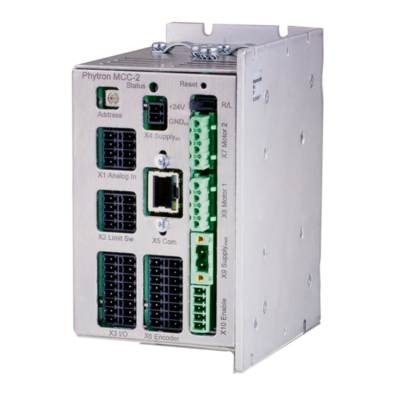
- Page 1 MCC-2 Programmable Stepper Motor Controller for Two Axis MANUAL 1235-A016 EN Extreme. Precision. Positioning.
- Page 2 MCC-2 Programmable Stepper Motor Controller for Two Axes TRANSLATION OF THE GERMAN ORIGINAL MANUAL 6/2018 Manual 1235-A016 EN...
- Page 3 Furthermore we reserve the right to make improvements and enhancements to the manual and / or the devices described herein without prior notification. You find the updated version of this manual on the website of www.phytron.de. We appreciate suggestions and criticisms for further improvement. Please send your comments to the following email address: doku@phytron.de...
-
Page 4: Table Of Contents
Contents 1 The MCC-2 Stepper Motor Controller ..4 6.3.1 X4 Power Supply I/O ....... 27 Overview ..........4 6.3.2 X9 Supply Voltage PWR ....28 Structure of the Device ......5 X7/X8 Motor Connector ...... 29 1.2.1 Stepper Motor Power Stages ... 6 6.4.1 Stepper Motor Connection .... -
Page 5: The Mcc-2 Stepper Motor Controller
The program will be stored and can be locally started by the REMOTE/LOCAL switch. MCC-2 and stepper motors need a DC power supply from 24 to 48 V A separate 24 V supply voltage is required for the outputs and limit switches. -
Page 6: Structure Of The Device
Please mention for all connector figures in this manual: When the controller is placed in such position that the MCC-2 designation is at the right upper edge, the upper pin in the drawing also is the upper pin at the device. -
Page 7: Stepper Motor Power Stages
1.2.2 Inputs and Outputs MCC-2 can be regarded as independent machine controller because of eight digital inputs, which are electrically separated from the sequential controller, and eight overload-safe outputs. -
Page 8: Interfaces And Bus Mode
• Test mode and status information • Firmware update • Controller communication via Ethernet The MCC-2 can be programmed user-friendly by MiniLog-Comm for Windows (see manual MiniLog-Comm). 1.2.4 REMOTE/LOCAL-Switch R/L You can select the controller's operating mode with the REMOTE/LOCAL switch: REMOTE: The controller is connected to the PC via interface. -
Page 9: Address Switch
Manual MCC-2 1.2.6 Address Switch The logic device address can be selected by the address switch and set from 0…F. This rotary switch is only read after power on or after a reset, i.e. later changes remain without effect during the regular operation. -
Page 10: Extent Of Supply
#10021217 with Ethernet connection for rail mounting #10021212 Included in delivery: • MCC-2 Manual • MiniLog Programming Manual • MiniLog-Comm Manual • Phytron CD with MiniLog-Comm software Fig. 4: MCC-2 with USB converter and RS 485 interface MA 1235-A016 EN... - Page 11 Manual MCC-2 Supplementary parts are available: • Rail mounting kit #02005659 • Mating connector kit (X1 to X4, X6 to X10) #10005871 • Cable (connection A-A) 20 cm #10006857 • Cable (connection A-A) 100 cm #10006880 • USB cable (connection A-B) 200 cm #10006881 •...
-
Page 12: Accessories: Operator Panel
1.5 Accessories: Operator Panel A MCC-2 with RS 232 adaptor is used for operator panel connection (e.g. BT 5). The terminal is connected to the RS 232 connector of the adaptor. You'll find the description of the operator panel in Phytron's manual 'Operator Panel BT 5'. -
Page 13: Directives And Standards
The instructions provided in “Installation” must be complied with to guarantee that the MCC-2 is EMC compliant when fitted in the machine or installation and before use of the device is permitted. -
Page 14: Declaration Of Incorporation
1.7 Declaration of Incorporation MA 1235-A016 EN... -
Page 15: To Consider Before Installation
Observe the safety instructions in the following chapter! 2.1 Qualified Personnel Design, installation and operation of systems using the MCC-2 may only be performed by qualified and trained personnel. These persons should be able to recognize and handle risks emerging from electrical, mechanical or electronic system parts. -
Page 16: Safety Instructions
2.2 Safety Instructions The MCC-2 is designed for operating as a wall or rail mounting device. An installation is only allowed, if the requirement of the EC Machine Directive and EMC are conformed with. See chap. 1.6. This product is used as a part of a complete system, therefore risk evaluations must be made before the use of the product regarding the concrete application. -
Page 17: Ambient Conditions
The maximum voltage limits are the specified values of the corresponding chapters. WARNING Danger of injury if touching the surface! The surface of the MCC-2 reaches temperatures more than 75 °C during operation. The controller has to be deactvated at temperatures more than 75 °C. 2.3 Ambient Conditions... -
Page 18: Protective Measure Options
3 Protective Measure Options The control unit must be operated by the protective measure PELV acc. to VDE 0100. Board and motor housing have to be grounded and/or connected to 0 V. Various options are possible to achieve the protective measure PELV: Fig. - Page 19 Manual MCC-2 If there is no PE clamp on the motor, the 0 V wire must be grounded to complete the protective measure PELV (Fig. 10 and Fig.11): Fig. 10: PELV – Grounding: 0 V and Controller Fig. 11: PELV – Grounding: 0 V...
-
Page 20: Design Requirements
4 Design Requirements 4.1 Electromagnetic Compatibility (EMC) 4.1.1 Remarks WARNING Risk of injury by interference of signals and devices! Perturbed signals can cause equipment to react unexpectedly. • Connect the controller to the EMC requirements. • In electrically noisy environments ensure the correct execution of the EMC measures. - Page 21 Use the cable clamps at the bottom and the top side of the MCC-2. Remove the external cable sheath in that range of the cable where you fix it with one of the cable clamps.
-
Page 22: Cables
4.2 Cables maximum cable minimum cross shielded, grounded length section on all sides Motor cable The length depends on Dependent on the the cable resistance: maximum current of the motor and the < 0.2x cable motor cable length is... -
Page 23: Technical Data
(labeling readable) because of a better heat dissipation. The clip for rail mounting is mounted on the rear side. Accessories (optional) MCC-2 with additional RS 232 port for connecting a BT 5 operator panel MCC-2 with attached USB converter Fig. 12: Dimensions in mm •... -
Page 24: Electrical Data
5.2 Electrical Data Technical Characteristics Supply voltage Unregulated filtered DC voltage Admissible voltage range for • Controller and motor: 24 to 48 V (X9) • Limit switch and outputs: 24 V ( X4) Reinforced or double insulation between mains and secondary circuit is required. - Page 25 Manual MCC-2 Technical Characteristics Error detection The MCC shuts down in case of undervoltage 17 V ±1 V. The error is set by the status bit and is indicated by the status LED which can be reset by a hardware or software reset (power stage reset).
-
Page 26: Installation
6 Installation 6.1 Mechanical Installation DANGER Danger of electric shock in case of foreign particles or damage! Make sure during the installation that not fixed particles, such as pieces of wire or assembly parts, can fall into the device. Conductive foreign materials in the product can endanger persons in case of parasitic voltage and destroy the device by short circuit. - Page 27 Manual MCC-2 Fig. 13: Wall mounting MCC-2, dimensions Fig. 14: Rail mounting MCC-2, dimensions MA 1235-A016 EN...
-
Page 28: Electrical Installation
6.2 Electrical Installation Connectors - Overview Connector Number Phoenix connector Phoenix mating Material number of poles type connectors (mating connector) X1 / X2 2 x 4 MCDN 1,5/4-G1-3,5 FMC 1,5/4-ST-3,5 #10005880 P26THR X3 / X6 2 x 8 MCDN 1,5/8-G1-3,5... -
Page 29: X9 Supply Voltage Pwr
24 to 48 V Fig. 16: X9 Connector Supply PWR • When the MCC-2 is supplied by means of an unregulated filtered DC voltage (e.g. transformer), a load capacitor of min. 3,000 μF should be used. • Protective ground of the supply voltage should be connected to the earthing screw on the upper or lower side of the device. -
Page 30: X7/X8 Motor Connector
The current can be set less exactly, if the current value is smaller than 600 mA. We recommend to use the linear MCC-2 LIN controller if the accuracy of the motor current setting must be improved. MA 1235-A016 EN... -
Page 31: Wiring Schemes For 2-Phase Stepper Motors
Manual MCC-2 6.4.2 Wiring Schemes for 2-Phase Stepper Motors Fig. 18: Wiring schemes for 2-phase stepper motors WARNING Motor leads not used should be individually isolated (e.g. 6-lead motors)! MA 1235-A016 EN... -
Page 32: Motor Cable
Use the cable clamps at the bottom and the top side of the MCC-2. Remove the external cable sheath in that range of the cable where you fix it with one of the cable clamps. -
Page 33: X5 Com Communication Interface
• is assigned via Minilog Comm or phyLOGIC ToolBox (Interface parameter/Eth-MCM menu). When the MCC-2 is connected to the PC by USB-interface, USB drivers have to be installed on the PC. An USB converter is needed, if several controller should be connected by USB. - Page 34 USB Interface MCC-2 and PC can be directly connected by the USB cable type A-B. The USB port of the PC (type A) is directly connected to the USB port of the controller (type B). The MCC-2 operates in the stand-alone mode.
-
Page 35: Ethernet Interface
Manual MCC-2 • When the MCC-2 is connected to the PC by USB-interface, USB drivers have to be installed on the PC. • Administrator authorizations are required for the driver installation. • Use a USB cable with a maximum length of 2 m! •... -
Page 36: Rs 485 Interface
↔ RS 485 bus PC with RS 485/4-wire- or RS 422 interface The figure below shows the RS 485 bus connection to MCC-2 by a RS 422 or RS 485/4- wire interface on PC. Fig. 24: Connection PC (RS 422/485 interface ... - Page 37 MCC-2 must be inserted. Fig. 25: Bus connection PC MCC-2 with USB-RS 485 converter in RS 485 mode The figure below shows the connection of the PC to MCC-2 by the Phytron USB-RS 485 converter.
-
Page 38: Rs 232 Interface
6.5.3 RS 232 Interface The MCC-2 can be used as single device by RS 232 interface. Fig. 27: 9 pole D-sub male connector acc. to DIN 41652 The following figures point out the cable connections to a PC with RS 232 interface. -
Page 39: Signal Interface Connection
The X1 analog inputs can be used for voltage measurement, as well as e.g. for a joystick as AD converter. The 5 V ±3 % / max. 100 mA voltage is supplied by the MCC-2. Input voltage: 0 to 5 V Resolution: 10 Bit A/D conversion time: about 15 µs... -
Page 40: X2 Limit Switch Input
CAUTION Danger of device damage! Do not exchange X1 and X2! 6.6.3 X3 Digital Inputs/Outputs MCC-2 controllers have each eight digital electrically insulated inputs and outputs. Fig. 32: X3 Pin assignment CAUTION Danger of device damage! Do not exchange X3 and X6! - Page 41 Manual MCC-2 Inputs The inputs are connected to a common ground connection (GND at X2, X4 or GND at X9). Input level: 24 V The input circuit protective resistor of 3.3 kΩ corresponds to 7 mA nominal driver current at 24 V Signal level Low: <...
-
Page 42: X6 Encoder Connector
6.6.4 X6 Encoder Connector • Connection of one encoder per axis. • Incremental encoder with quadrature signals or absolute encoder acc. to SSI- standard. • The following encoders can be evaluated: SSI protocol resolution n max. SSI1 n=22 SSI5... - Page 43 Manual MCC-2 CAUTION Danger of device damage! Do not exchange X3 and X6! Danger of damage! Connect the correct encoder type! Do not parameterize an incremental encoder as SSI. Fig. 36: Wiring of incremental encoder Fig. 37: Wiring of SSI absolute encoder...
-
Page 44: X10 Enable Connector
6.6.5 X10 Enable Connector • The power stage can be deactivated independent of the logic signals (enable connector X10). • Two opto-decoupled Enable inputs are used to activate the motor supply. Both Enable inputs must be wired for activation! •... - Page 45 Manual MCC-2 Fig. 40: Enable connector wiring MA 1235-A016 EN...
-
Page 46: Putting Into Service And Test
Advanced >> The baud rate in the controller can be changed by clicking on and can be Set! saved by Baud rates MCC-2 can be selected in menu item Options/Interface parameters or by programming instruction 9 600 38 400 14 400... -
Page 47: Test Stepper Motor(S), I/Os And Limit Switches
25 = 2.5 A r.m.s. r.m.s. In menu item Transmission/Send/Parameter the parameter list is saved in the MCC-2. On delivery the following settings are valid: Run current: 0.6 A, stop current: 0.2 A, boost current: deactivated Set motor currents corresponding to the motor winding parameters! See chap. - Page 48 The corresponding instruction for the other motor would be: Y+200. 8. An icon in the menu bar Transmission/Operation opens the following dialog box which enables you to drive the motor per mouse click. Axis1– (X–) Axis2+ (Y+) 9. Click on simply one of the buttons .
-
Page 49: Programming
(see MiniLog programming manual). MCC-2 controller can store MiniLog programs up to 128 kB program memory. For editing and managing MiniLog programs, the MiniLog-Comm communication software for PC is delivered together with the controller. -
Page 50: Heating Curve Of Mcc-2
In practice it can differ from the diagrams below. The housing temperature should not exceed 75 °C (measured on the right side of the housing and MCC-2 vertically arranged). In order to prevent destruction of the hardware, the internal emergency cutout shuts down actively at higher temperature. - Page 51 Manual MCC-2 Normalized housing temperature, half current, 100% duty cycle Fig. 42: Heating curve for one/two axes operation and half current Normalized housing temperature, half current, 60% duty cycle Fig. 43: Heating curve for one/two axes operation and 60 % duty cycle...
-
Page 52: Warranty, Trade Marks And Protective Measures
In this chapter warranty, trade marks and ESD protective measures are described. 10.1 Warranty The MCC controllers are subject to legal warranty. Phytron will repair or exchange devices which show a failure due to defects in material or caused by the production process. This warranty does not include damages which are caused by the customer, as there are, for example, not intended use, unauthorized modifications, wrong treatment or wrong wiring. -
Page 53: Index
Manual MCC-2 11 Index AD converter 38 LabVIEW 48 Address switch 8 LED 8, 45 Limit switch 6, 27, 39, 46 LOCAL 7 Low voltage error 6 Baud rate 32 Boost current 46 MiniLog 48 MiniLog-Comm 4, 8, 41, 46... - Page 54 Run current 46 Trade marks 51 Run frequency 23 Undervoltage 24 Screws 25 USB 7, 32, 33 Shielding mesh 20, 31 USB-driver 32 Step resolution 23 Stepper motor 23, 29 Stop current 46 Virtual instrument 48 Supply voltage 23...
- Page 55 Phytron, Inc. 600 Blair Park Road, Suite 220 Phytron GmbH Williston, VT 05495, USA Industriestraße 12 – 82194 Gröbenzell T +1-802 872-1600 F +1-802 872-0311 T+49-8142-503-0 F +49-8142-503-190 www.phytron.com www.phytron.de...
Need help?
Do you have a question about the MCC-2 and is the answer not in the manual?
Questions and answers