Table of Contents
Advertisement
Quick Links
Instruction manual
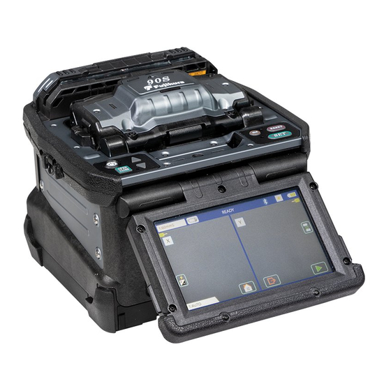
Core Alignment Fusion Splicer 90S
Please don't ship the 90S to an end customer until October 25 due to IP issue.
From October 26, it is possible to ship the 90S for an end customer with NDA
between distributor and customer.
Please don't publicize the information of 90S/R until a press release date on
December 6.
FUSION SPLICER 90S RevT1
Tentative version
Please read this instruction manual carefully
before operating the equipment.
Adhere to all safety instructions and
warnings contained in this manual.
Keep this manual in a safe place.
There is a change without a previous notice.
We are not responsible for the products
which are not purchased from our authorized
distributors.
Advertisement
Table of Contents

Related Manuals for Fujikura 90S


Summary of Contents for Fujikura 90S
- Page 1 Please don't ship the 90S to an end customer until October 25 due to IP issue. From October 26, it is possible to ship the 90S for an end customer with NDA between distributor and customer.
- Page 2 FUSION SPLICER 90S RevT1 Please consent beforehand. The software equipped in splicer and its related documents are protected by copyright laws and international treaty provisions as well as other intellectual property laws. Copying some or all of instruction manual without notice is forbidden without explicit permission from our company.
-
Page 3: Table Of Contents
FUSION SPLICER 90S RevT1 Wireless communication with tools ..............28 Wind-protector automatic opening-and-closing function ........28 Table of Contents Operation mode ....................29 Selection of the operation mode ..........29 Safety Information ....................4 Bluetooth ® Wireless Technology ................7 How to change the operation mode .......... - Page 4 FUSION SPLICER 90S RevT1 Select Splice Mode ..............57 Battery Discharge ....................78 Motor Drive ......................78 Editing Splice Mode ..............59 Maintenance Info ....................78 Splice Settings Menu .................... 79 Initializing edited parameters ............60 Composition of the Splice Settings Menu ............79 How to change the settings .................
-
Page 5: Safety Information
Do not attempt to use this machine for other Disconnect the AC power cord from the AC adapter inlet or the wall applications.Fujikura Ltd. gives much consideration and regard to personal socket (outlet) immediately if user observes the following or if the injury and any damages. - Page 6 When using an AC generator with AC output voltage immediately wash skin or eyes thoroughly and see the doctor. of AC220-240V especially, Fujikura Ltd. recommends the following Dispose of the battery and call the service center for replacement.
- Page 7 FUSION SPLICER 90S RevT1 CAUTIONS! RECYCLING and DISPOSAL Do not store splicer in any area where temperature and humidity are extremely high. Possible equipment failure may result. In European Union In accordance with the European Parliament Directive 2002/96/EC, Do not touch protection sleeve or tube-heater during heating or electrical parts and materials that can be re-used and/or recycled have immediately after completion of heating.
-
Page 8: Bluetooth® Wireless Technology
RE Directive: 2014/53/EU EN300 328, EN301 489-1, EN301 489-17 and EN 60950-1 JAPAN Radio-wave Law Article38-24 paragraph 1 R209-J00255 ・ If you have any questions for other countries, contact an authorized Fujikura distributor listed in the following web site: https://www.fusionsplicer.fujikura.com/service/index.html... -
Page 9: General Information
FUSION SPLICER 90S RevT1 General information LCD monitor Introduction This splicer is equipped with an LCD monitor. LCD monitos are This fusion splicer can splice a single optical fiber. Moreover, new functions manufactured at a high quality factory, but the pixels of the LCD monitor may were added and made the splicer much improved in versatility. -
Page 10: Upgrade Of Software
FUSION SPLICER 90S RevT1 Upgrade of software Convenient usage of wireless data communication function with cleaver CT50 The firmware of the splicer can upgrade to the latest version on the Internet It is difficult for operators to track blade wear. However, it is easy to detect using the “Data Connection”... - Page 11 FUSION SPLICER 90S RevT1 Convenient usage of wireless data communication function with the ribbon stripper RS02/03 Using a fiber holder, a fiber with 200 to 400 umm coating diameter can be stripped by a rebbon fiber stripperr. This fusion splicer also performs wireless communication with RS03.
-
Page 12: New Sheath Clamp
FUSION SPLICER 90S RevT1 New sheath clamp Fiber retention clamp Easy sleeve positioning clamp The “fiber retention clamp” enables to hold fibers even if sheath clamp open. It is useful for automatic wind protector function. The sheath clamp is optimized for the 60mm length sleeve. In case of using You can select the function ON/OFF by the yellow/green switch. -
Page 13: Touch Panel Display & New Designed Menu Screen
FUSION SPLICER 90S RevT1 Corresponds to loose tube fiber Touch Panel Display & New designed Menu Screen The splicer has a touch panel display and new designed menu. The operator The sheath clamp has the protrusion part inside to splice the loose buffer can select or change the setting immediately by pressing the icons in the cable. - Page 14 FUSION SPLICER 90S RevT1 Power supply connector for the device The USB connector of this splicer can supply the power to the device like a LED lamp or a cell phone *1 LED lamp Cell phone Connector type Current capacity USB 2.0 Type A...
-
Page 15: Newly Designed Carrying Case And Work Tray
FUSION SPLICER 90S RevT1 Newly designed carrying case and work tray Work tray Carrying case The work tray has two drawers for storing the tools without dust The drawers are The new carrying case has a large space inside, allowing you to store all the tools just the right size for tools or battery pack. - Page 16 FUSION SPLICER 90S RevT1 Protection sleeve stand The work tray has a stand to place the protection sleeve after heating process. Protection sleeve stand can be detached. Configuration1 Configuration 2 Detouchable sleeve stand Drop cable holding stand The work tray has a stand for placing the drop cable clamp (CLAMP-12DC).
-
Page 17: Description Of Product
FUSION SPLICER 90S RevT1 Description of product Components of splicer The standard package of the splicer is the following. Check the equipment items mentioned of list. Standard package list (2 of 2) Standard package list (1 of 2) Single Fiber Stripper... -
Page 18: Other Necessary Items For Splicing Operation
FUSION SPLICER 90S RevT1 Other necessary items for splicing operation Fiber UV coating Nylon coating coating 250µm 900µm diameter [FH-70-250] [FH-70-900] Fiber holder (Option) * Old model [FH-60-250] can * Old model [FH-60-900] can also be used. also be used. -
Page 19: Description Of Splicer
FUSION SPLICER 90S RevT1 Description of Splicer Structure Side Front Tube Heater Wind protector LCD monitor Battery slot Wind protector USB B Mini For Ribbon sripper USB A RS02/RS03... - Page 20 FUSION SPLICER 90S RevT1 Inside of Wind protector V-groove illumination Electrode Sheath clamp V-groove V-groove Electrode Clamp Clamp...
- Page 21 FUSION SPLICER 90S RevT1 Operation of sheet key UP key ON/OFF key HEAT key RESET key DOWN key OPEN/CLOSE key SET key Key name Key function OPEN/CLOSE To open and close the wind-protector. ON/OFF key To turn ON/OFF the power.
-
Page 22: Basic Operation
FUSION SPLICER 90S RevT1 Basic Operation In the case of use only with splicer Splicing work preparation Use in a location which does not have vibration, a shock, etc. at the time of performing fusion splice work. In work [at the unstable place where a main part is Multiple work environment configurations can be created using the carrying shaky], the possibility of damage from a fall becomes high. -
Page 23: Power Supply
FUSION SPLICER 90S RevT1 Power supply AC Operation The power supply of a splicer can be operated with AC power supply and a battery. 1. When operating the splicer with AC power, use the AC adapter (ADC-20), DC adapter (DCA-03) and AC power cord (ACC-xx). -
Page 24: Dc Operation With External Battery
FUSION SPLICER 90S RevT1 DC operation with external battery Battery Operation 1. When operating the splicer with DC power, use the DC adapter (DCA-03) Please use the supplied battery pack BTR-15. and DC cord (DCC-20 or DCC-21). 2. Insert the DC adapter into the splicer body. - Page 25 FUSION SPLICER 90S RevT1 How to check remaining battery capacity by the splicer display How to check remaining battery capacity by the battery pack If splicer is already equipped with the battery, turn splicer ON. Power If battery is not inserting in the splicer, simply press the battery check push source of "Battery"...
-
Page 26: Turning Splicer On/Off
FUSION SPLICER 90S RevT1 Turning Splicer ON/OFF How to charge the battery Turning Splicer ON Plug the AC power cord (ACC-xx) into the inlet of the AC adapter (ADC-20). Press ON/OFF key and hold it until the green LED turns on. The Plug the supply terminal of AC adapter following warning screen is displayed. - Page 27 FUSION SPLICER 90S RevT1 Heater Calibration function When you kept the splicer with powered-off for 1 week or longer, the Heater Calibration function automatically starts after booting up. During this process, “X” mark appears on the heater icon as below.
-
Page 28: Splicer Settings Check / Ready Screen
FUSION SPLICER 90S RevT1 Splicer settings check / READY screen Icon name Key Function Composition of a READY screen After selection, “Arc Calibration” function in Arc Calibration [Maintenance] can be selected directly. The number of the arc discharging in Arc Count [Maintenance] is displayed. -
Page 29: Lcd Brightness Adjustment
FUSION SPLICER 90S RevT1 LCD Brightness Adjustment Wind-protector automatic opening-and-closing function Monitor visibility changes depending on environmental conditions. To change If the OPEN/CLOSE key is pressed on a READY screen, the wind-protector will monitor brightness, press the light icon at the upper right side on READY open or close. -
Page 30: Operation Mode
FUSION SPLICER 90S RevT1 A continuation of the operation mode parameter Operation mode Parameter Description Selection of the operation mode Operation mode Each operation mode consists of parameters shown below so that operation of the equipment before and after of work can be set up. -
Page 31: How To Change The Operation Mode
FUSION SPLICER 90S RevT1 How to change the operation mode Select of the Splice mode Touch the Home icon on [Ready] screen, a [Main menu] sceen will be displayed. Touch the Splice setting icon to enter the [Splice setting] screen The optimal splice setting for a specific fiber combination consists of the splicing and touch the “Operation mode”... -
Page 32: How To Check The Splice Mode
How to check the splice mode The current splice mode is displayed in the monitor as shown below Each tube-heating mode is optimized for a type of Fujikura protection sleeve. These modes can be found in database area for reference. Copy the appropriate one and paste it to the user-programmable area. -
Page 33: How To Check The Current Heater Mode
Tension member Sleeve length When using a protection sleeve which is not made by Fujikura, please set parameters based on the specific sleeve. When the sleeve of another company is used, the durability of a protection point cannot be warrantied. -
Page 34: Preparation Of Fiber
FUSION SPLICER 90S RevT1 Preparation of fiber Fiber Cleaving when using a sheath clamp Cleaning optical fiber Take out the CT50 from the carrying case and release the lock from the Clean optical fiber with alcohol-moistened gauze or lint-free tissue approximately lever. -
Page 35: Fiber Cleaving When Using A Fiber Holder
FUSION SPLICER 90S RevT1 Fiber Cleaving when using a Fiber Holder Close and gently push down on the Lever until it stops. The blade Set the Fiber holder set Plate(SP-03) automatically moves and cleaves the fiber. Lift the Lever until it stops and remove the fiber from the cleaver. Be careful Loosen the 3 screws and remove each sheath clamp from the splicer. - Page 36 FUSION SPLICER 90S RevT1 Set the fiber onto fiber holder In case of Fiber holder “FH-60 series” 1. Open the lid of a fiber holder and then set the fiber onto the fiber holder. Set the fiber onto the fiber holder with the fiber sheath 3.0mm from the edge of the fiber holder.
-
Page 37: Loading Fiber To Splicer
FUSION SPLICER 90S RevT1 Push the fiber holder towards. Check the position of the fiber coating. If it sits Loading fiber to splicer on the rubber pad, adjust the fiber position in the Fiber Holder until it doesn’t sit Using sheath clamp on the pad. -
Page 38: Wind-Protector Motion And Sheath Clamp Motion
FUSION SPLICER 90S RevT1 Wind-protector motion and sheath clamp motion Arc Calibration Atmospheric conditions such as temperature, humidity, and pressure are This unit has the Wind-Protector automatic opening-and-closing constantly changing, which creates variability in the arc temperature. This splicer mechanism and switching action differs by the chosen operation mode. -
Page 39: Splicing Procedure
FUSION SPLICER 90S RevT1 Use standard SMF ITU-T G652 fiber for Arc Calibration. In some cases, multiple iterations of arc calibration are needed until Use well prepared fibers for arc calibration. Dust on the fiber the calibration process is successfully completed and the "Test surface affects arc calibration. - Page 40 FUSION SPLICER 90S RevT1 If no error message is displayed, the end-face conditions are used for visual inspection as shown below. If observed, remove the fiber from the Estimated splice loss is displayed upon completion of splicing. Splice splicer and repeat fiber preparation. These visual defects may cause a loss is affected by certain factors stated.
- Page 41 FUSION SPLICER 90S RevT1 Splice loss increase: Cause and remedy (2 of 2 ) Restriction of the number of times of additional arc discharge can be set up. Symptom Cause Remedy Since excessive additional arc discharge becomes the cause of...
-
Page 42: Storing Splicing Results
FUSION SPLICER 90S RevT1 Storing splicing results Splicing results is stored in memory. A vertical line sometimes appears at the splice point when MM fibers or dissimilar fibers (different diameters) are spliced. This does not affect splice quality, such as splice loss or tensile strength. -
Page 43: Fiber Proof Test
FUSION SPLICER 90S RevT1 Fiber proof test Heating protection sleeve The strength of the splice point can be checked. After splicing when a proof-test is performed by pressing the SET key or opening wind-protector. If the operation When using 60mm length sleeve mode is set to “Auto”... - Page 44 FUSION SPLICER 90S RevT1 When using short length sleeve less than 60mm 4. The sleeve slide and reach to the left hand. When use the 40mm length sleeve or micro sleeve, using sleeve scale on the surface of theater would be convenient.
-
Page 45: Maintenance Of Splicing Quality
FUSION SPLICER 90S RevT1 Maintenance of Splicing Quality Cleaning and Checking Before Splicing After setting fiber to the heater, the heater lid automatically closes. Keep It is possible to maintain the performance of the splicer for a long time with applying tension to the fiber until then. -
Page 46: Periodical Checking And Cleaning
FUSION SPLICER 90S RevT1 Cleaning V-groove Clamp Chips Periodical checking and cleaning In order to maintain the splicing quality of the splicer, periodic inspection and If contaminants are present on the clamp cleaning are recommended. chips, proper clamping may not occur, resulting in poor quality splices. - Page 47 FUSION SPLICER 90S RevT1 Protrusion of the sheath clamp for loose tube Change the cleaver CT50 blade position The sheath clamp equips protrusion for loose tube fiber. The cleaving of the end face deteriorates when the cleaving blade wears. The The protrusion enables to hold fber clamp loose tube fiber.
- Page 48 If an error occurs when attempting to rotate the blade, the Batt. LED indicator will blink red. In this case, close Lever and repeat. If same problem happens, contact a Fujikura authorized distributor. Method3: Rotate the blade manually by Blade Rotating Dial.
- Page 49 After the circular blade has been raised 2 times and rotated through all 3 positions (a total of approximately 60,000 for CT50 fiber cleaving), it needs to be replaced. The user can replace the cleaver blade. Contact to Fujikura authorized distributor.
-
Page 50: Wireless Data Communication
FUSION SPLICER 90S RevT1 Wireless data communication Wireless data communication function of the splicer icon Description The splicer features wireless data communication with the optical fiber cleaver When the [Splicer] in Bluetooth menu is set (CT50) and optical fiber stripper (RS03) via Bluetooth. This capability allows “ON”, this sign appears. -
Page 51: How To Check The Communication Status With Stripper & Cleaver50
How to establish wireless data communication How to check the communication status with Stripper & Cleaver During the connection process, If purchased separately, the CT50, RS02/03 and compatible splicer will need RS03: The Link LED on the RS03 lights up. to be paired before cleaver management begins. -
Page 52: How To Turn Off The Wireless Data Communication
The cleaver or stripper that can be connected to the screen of the splicer is How to turn off the wireless data communication displayed in white, so please tap with your finger to pair. Please turn off the wireless data communication function when using this splicer in places where wireless data communication is prohibited. - Page 53 Procedures in case of Cleaver Procedure2 (In the case of RS03) ・ Remove the battery from the stripper to stop all communication. Procedure1 Remove the battery when transporting by aircraft. ・ Remove the battery from the cleaver to stop all communication. Remove the battery when transporting by aircraft.
-
Page 54: Blade Management Menu
Blade Management Menu Convenient usage of wireless data communication function By using the [Blade Management] menu, it is simple to check wear condition of Convenient usage with cleaver CT50 the cleave blade during splice operation. The splicer determines whether or not It is difficult for operators to track blade wear. - Page 55 Convenient usage with the ribbon stripper RS02/03 Using a fiber holder, a fiber with 200 to 400 umm coating diameter can be stripped by a rebbon stripperr. This fusion splicer also performs wireless communication with RS02/RS03. The ribbon fiber stripper settings are automatically changed according to the splice mode.
-
Page 56: Main Menu
Main Menu A continuation of icon list Composition of Main Menu Icon Name Description [Other Setting] screen appears. Other This allows review/edit the wireless communication and the Setting supervisor settings. [Guide/Promotion] screen appears. Guide It shows the procedure how to use this splicer with Built in instruction guide. -
Page 57: Splice Mode Menu
Splice mode menu Splice Mode Composition of Splice Menu The optimal splice setting for a specific fiber combination consists of the splicing Common parameters for all the modes for splicing can be set. parameters listed below. In other words, the optimal splicing parameters [Splice Mode] screen appears when selecting the Splice Mode icon at depend on the fiber combinations, and are different from fiber to fiber. -
Page 58: Select Splice Mode
Database of splice mode (AUTO) Below is a figure showing the Arc discharge conditions (relationship between "Arc power" and "Motor motion"). The conditions can be edited by changing Splice mode Description the splicing parameters listed below. Depending on splice mode, certain This splice mode can splice standard telecommunications grade parameters cannot be changed. - Page 59 Special splice mode Fast splice mode In this mode, the parameters are set in detail and can be changed. Use this splice mode when need to change the parameter setting, for example, Use this mode if the fiber type is identified and prefer quick splice with high yield to consistent splice loss.
-
Page 60: Editing Splice Mode
Attenuatino splice mode Editing Splice Mode Splicing parameters in each splice mode can be modified. Arc power and Arc Use this splice mode when you need intentionally splice loss by making axis offset. time are considered the two most vital parameters. Select AT1 or AT2 from Fiber type. -
Page 61: Initializing Edited Parameters
Initializing edited parameters Edited parameters can easily be initialized to their preset parameters by performing the following procedure: 1. Press icon. 2. Enter the [Fundamental Settings] screen. 3. Select Fiber Type icon and select the same Fiber Type. 4. All parameters are overwritten by the factory value in the data base. -
Page 62: Creating Or Deleting Splice Modes
Creating or deleting splice modes How to erase splice mode How to create a splice mode Splice mode can be erased. Follow the below steps to erase splice mode. There are necessary splice modes stored when the splicer is first delivered, and all the other modes are displayed [BLANK]. -
Page 63: Detail Of The Parameters In Splice Mode
Detail of the parameters in splice mode Parameter Description AUTO mode and FAST mode: [** AUTO], [** FAST] Error Limit Below is a list of Splicing parameters for AUTO modes and FAST mode. Cleave Angle Error message is displayed if the cleave angle of either Only a limited number of parameters listed below are displayed for those Limit the left or right fiber ends exceeds the selected threshold... - Page 64 Special mode: [SM], [NZ], [DS], [MM] Splicing parameters: standard modes Parameter Description In other splice modes in the user-selectable database, the user can select from a series of factory-set splicing modes for various splicing XY Aignment combinations. Below are the descriptions of the various parameters used Focus-L/R Sets the focal point for fiber observation.
- Page 65 Parameter Description Parameter Description Prefuse and Stuff Tapering Prefuse Sets the power of the prefuse arc, which is an arc discharge Splice loss is sometimes improved when the fiber is tapered Power occurring from the beginning until the fibers begin stuffing. (pulled) during arc discharge to make the splice thinner.
-
Page 66: Manual Splice Mode
Manual Splice Mode Parameter Description This mode is to manually align and splice fibers. The following procedure is Error Limit required, and is different from standard automatic splicing. An error message is displayed if the cleave angle of either Cleave Angle the left or right fiber ends exceeds the selected threshold Select a splice mode that allows the Limit... -
Page 67: Ecf Splice
ECF Splice Attenuation splice mode (AT1,AT2) When fibers having some core concentricity-error are aligned using the core-to- Attenuation splice mode makes an intentional core axial offset to create core method, their outer claddings are not aligned in line with each other as shown attenuation at the splice point. -
Page 68: Heater Mode Menu
Heater Mode Menu Select Heater Mode Each tube-heating mode is optimized for a type of Fujikura protection sleeve. Composition of the Heater Mode Menu These modes can be found in the database area for reference. Copy the appropriate one and paste it to the user-programmable area. The operator can Common parameters for all heating modes can be set in this menu edit the user-programmable modes. -
Page 69: Referring To Or Editing Heater Mode
Referring to or Editing Heater Mode The dimensions of the Protection Sleeve after heat shrink Diameter of an Tube-heating conditions stored in heater mode can be edited or changed Tension Sleeve Prepare fiber Diameter of Form adaptation member length length a result optical fiber Select the... -
Page 70: Initialization Edited Parameters
Initialization edited parameters Creating and Deleting Heater Mode Tube-heating conditions stored in heater mode can be edited or changed Creating heater modes There are necessary heater modes stored when the splicer is first delivered, Select the icon in the [Heater Mode] menu, to show the heater and all the other modes are displayed [BLANK]. -
Page 71: Detail Of The Parameter In Heater Mode Menu
Detail of the parameter in Heater Mode Menu Deleting Heater Mode Heater mode can be erased. Follow the below steps to erase heater mode. The parameters in the Heater Mode Menu are listed below: Parameter Description Select the icon in the [Heater Mode] menu, to show the heater mode. -
Page 72: Tube Heating Drop Cable
Tube heating Splice-on-Connector Be careful not to twist fiber especially for using drop cable. This splicer is applicable to tube-heating for splicer-on-connector. In case of Fujikura Fuse Connect, removing the right clamp of the heater is necessary as below. Remove heater clamp... -
Page 73: Memory Menu
Memory Menu Review, editing, and deletion of splice results Composition of the Memory Menu Splicing results stored in the memory can be displayed. Comments can be added or edited. This splicer stores up to 20,000 splice results. Contents of splice data stored vary depending on the splice mode. -
Page 74: Splice Result Error
Delete of splice result data How to store the Camera Image Data Please refer to the above to display the splice memory. Select a specific memory number location where there is no image already Select the desired target result and click the icon stored. -
Page 75: Maintenance Menu
Maintenance Menu Arc Cairation Composition of the Maintenance Menu Atmospheric conditions such as temperature, humidity, and pressure are Common parameters for all the modes for Maintenance Menu can be set. constantly changing, which creates variability in the arc temperature. This [Maintenance Menu] screen appears when selecting the Maintenance Menu icon splicer is equipped with a temperature sensor that is used in a constant at the [Main Menu] screen. -
Page 76: Diagnostic Test
Diagnostic Test “Good” Message The splicer has a built in diagnostic test feature that allows the operator to Arc power and splicing position calibration have successfully completed. perform a simple one step evaluation of splicer performance covering several Press RESET key to exit. different critical variables. -
Page 77: Dust Check
Dust Check Motor Calibration The splicer observes fibers through image processing. Dust or contaminants on Motors were adjusted at the factory before shipping. However, motor the cameras and lenses may interfere with normal observation of fibers and performance could change due to various reasons. This function degrade splice quality. -
Page 78: Replace Electrodes
Replace Electrodes Clear Arc Count When the number of arc discharges reaches the setting value, a message This function enables the stored number of arc discharges to be reset. prompting to replace the electrodes is displayed immediately after turning on the Select the Clear Arc Count icon. -
Page 79: Battery Discharge
Battery Discharge Maintenance Info This function can discharge the battery pack. The maintenance information is displayed in the Maintenance Info screen. If there is some gap between the battery indicator and the actual capacity, perform When pressing Next Page icon, “Software License” page appears. this function to readjust the battery indicator. -
Page 80: Splice Settings Menu
Splice Settings Menu List of Splicing Settings parameters Composition of the Splice Settings Menu Common parameters for all splice modes can be set. Parameter description Fundamental settings [Splice Settings] screen appears when selecting the Splice Settings icon at Operation Automated wind-protector has several operation modes. [READY] screen. - Page 81 Parameter description Fiber Image on Screen Sets the method of displaying the fiber image on the screen Gapset during Splicing operation. Aligning X: Enlarged display of X-axis image Y : Enlarged display of Y-axis image X▲▼Y: Composite display vertically of X-axis and Y-axis Estimation images Pause1...
-
Page 82: Other Settings Menu
Other Settings Menu Machine Settings Composition of the Other Settings Menu Basic operation and maintenance parameters can be changed in this menu. Common parameters for all the modes for Other Settings Menu can be set in this menu. Select the Other Settings icon at [Main Menu] screen to enter this menu. The list of warning and maintenance parameters in this menu follow: Parameters List of the Machine setting menu (1 of 3 ) Detail of the Other Settings Menu... - Page 83 Parameters List of the Machine setting menu (2 of 3 ) Parameters List of the Machine setting menu (3 of 3 ) Parameter Description Parameter Description Cleaver Blade Alarm Power Saving Timer (with Battery) (with AC Adaptor) Determines if an alarm is set. (*1) Dimming Setting this function dims the brightness of the LCD Blade position Change...
-
Page 84: Supervisor Settings
This function enables switching between up to 12 "Boot Boot Password 1~12 Passwords" at different dates. For more details, refer to [About "Boot Password Password Boot Lock Variation"] on the following page. From 1~12 If you want to unlock the password, cotanct to Fujikura authorized distribututor. -
Page 85: About "Boot Password Variation
It is not necessary to input dates in order. The splicer sorts the passwords by date. In this example, the splicer uses "Boot Password 8" before "Boot If you want to unlock the password, contact to Fujikura authorized distributor. Password 7". - Page 86 The list of Menu Lock Settings parameters (1 of 2 ) The list of Menu Lock Settings parameters (2 of 2 ) Parameter Descriptions Parameter Descriptions Password Setting Splice Settings Sets a password to access the [Menu Lock Password] Splice Operation menus.
-
Page 87: Bluetooth Menu
Bluetooth Menu Cleaver Setting Menu This function configures the wireless data communication with the RS02/03 ribbon stripper or CT50 cleaver. This menu enables parameter selection to control the splicer interface with the CT50 cleaver. Regarding Bluetooth: The splicer features wireless data communication with the optical fiber cleaver (CT50) and optical fiber stripper (RS02/03) via Bluetooth. - Page 88 List of the Cleaver Settings parameters Parameter Description Alarm Settings *1 The wear of blade Blade Position ON/OFF setting enables or disables display of each The right figure shows the occurrence rate of bad cleaving. Change warning message for cleaver blade wear. If “OFF” is According to the graph, the rate is increases gradually.
-
Page 89: Stripper Setting Menu
Prameter list of Stripper Setting Stripper Setting Menu Parameter Descriptions This menu enables parameter selection to control the splicer interface with the ECO Settings RS02/03 ribbon stripper. Selects the machine to control the parameters in ECO mode of RS02/03. . [Stripper]: The parameters in ECO mode saved in the ECO Mode Control By internal memory of RS 02/03 are used. -
Page 90: Reference Guide
Reference Guide This menu shows the new features, the basic operation and information about this splicer. Select the Guide icon at [Main Menu] screen to enter this menu. -
Page 91: Instruction Manual And The Utility Software
PV can connect to internet or not at first. Note2: During installing this software, the software allows you to access to 3. Open the Windows Explorer on the PC. You will find an attached drive named Fujikura web site, “www.fujikura.co.jp/dev/splicers/ “, ask to “SPLICER”... -
Page 92: Error Message List
Error Message List When an error is in the list below, the splicer carries out operation which changes Press ENT when an error is shown on the monitor. The [HELP] screen displays with preset values of “Ignore Splicing Error”, when the operator presses the SET the following: key. - Page 93 Error Message List ( 1 of 8 ) Error Message List ( 2 of 8 ) Error Error Reason Solution Reason Solution Message Message ・ Press RESET key, and set ZL Motor L-Too Long ・ The fiber is not set correctly ・...
- Page 94 Error Message List ( 3 of 8 ) Error Message List ( 4 of 8 ) Error Error Message Reason Solution Reason Solution Message ZL/R ・ Assure the electrodes are in proper position. Focus X/Y ・ Consult the authorized No Arc ・...
- Page 95 Error Message List ( 5 of 8 ) Error Message List ( 6 of 8 ) Error Message Reason Solution Error Message Reason Solution ・ Calibrate the arc power with ・ Check the condition of the fiber ・ Inadequate arc power ・...
- Page 96 Error Message List ( 7 of 8 ) Error Message List ( 8 of 8 ) Error Message Reason Solution Error Message Reason Solution ・ Calibrate the arc power with ・ Clean the objective lenses by ・ Inadequate arc power. the [Arc Calibration] function.
-
Page 97: Questions And Troubleshooting
Splicing Operation Questions and Troubleshooting Error message appears on monitor Power Supply ・ Refer to [Error Message List] function. Power does not turn on when pressing ON/OFF key ・ The battery may not be charged. Charge is performed. Inconsistent splice loss / High splice loss ・... -
Page 98: Tube-Heating Operation
Heater LED on panel keyboard blinks Error message can be over-ridden ・ Pressing the HEAT key during heating causes the LED to blink. The tube ・ See Section [Splice Settings] to not allow error message override. heater is turned off if the HEAT key is pressed again. If, after 2 seconds have gone by without pressing the HEAT key again, the LED stays on continuously Unable to change Arc Power and Arc Time and the heater returns to its normal state. -
Page 99: Supervising
Bluetooth SIG, ® Inc. This logo and word appearing in this manual are trademarks or registered trademarks of their respective owners. Any use of such marks by Fujikura Ltd is Forgot password under license. -
Page 100: Guarantee And Contact Address
If the product fails due to defects or workmanship within the warranty period vibration and shock. When requesting splicer repair, please send it, along with stipulated by the Fujikura-authorized distributor, they will repair it free of charge. its accessories, in its original carrying case. -
Page 101: Contact Address
Contact Address Inquiries concerning products should be made to the authorized distributor or one of the following: Fujikura Europe Ltd. C51 Barwell Business Park Leatherhead Road, Chessington, Surrey KT9 2NY Tel. +44-20-8240-2000 (Service: +44-20-8240-2020) Fax. +44-20-8240-2010 (Service: +44-20-8240-2029) URL https://www.fujikura.co.uk...
Need help?
Do you have a question about the 90S and is the answer not in the manual?
Questions and answers
Kako nastaviš lokator baterije na zaslon
90s+ factory reset?