Table of Contents
Advertisement
Quick Links
ООО "Техэнком"
Контрольно-измерительные приборы и оборудование
www.tehencom.com
rd
3
Instruction manual
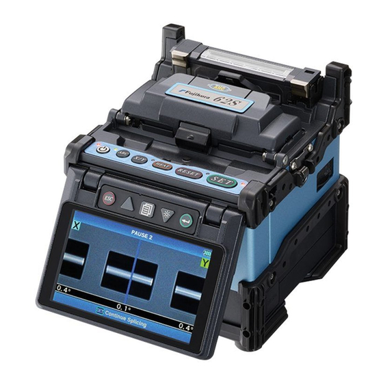
62S
Fusion Splicer
Please read this instruction manual carefully
before operating the equipment.
Adhere to all safety instructions and
warnings contained in this manual.
Keep this manual in a safe place.
There is a change without a previous notice.
We are not responsible for the products which are not
purchased from our authorized distributors.
Advertisement
Table of Contents

Subscribe to Our Youtube Channel
Related Manuals for Fujikura 62S


Summary of Contents for Fujikura 62S
- Page 1 ООО "Техэнком" Контрольно-измерительные приборы и оборудование www.tehencom.com Instruction manual Fusion Splicer Please read this instruction manual carefully before operating the equipment. Adhere to all safety instructions and warnings contained in this manual. Keep this manual in a safe place. There is a change without a previous notice. We are not responsible for the products which are not purchased from our authorized distributors.
- Page 2 ООО "Техэнком" Контрольно-измерительные приборы и оборудование www.tehencom.com Please consent beforehand. The software equipped in splicer and its related documents are protected by copyright laws and international treaty provisions as well as other intellectual property laws. Copying some or all of instruction manual without notice is forbidden. Moreover, without permission from our company, it cannot use on the Copyright Act except that it uses as an individual.
-
Page 3: Table Of Contents
ООО "Техэнком" Контрольно-измерительные приборы и оборудование www.tehencom.com Table of Contents Safety Information ............1 General information ............6 Introduction ...................... 6 Description of Product ............. 8 Components of Splicer ..................8 Other Necessary Items for Splicing Operation ..........10 Description and Function of Splicer ..............11 Operation of Sheet Key .................. - Page 4 ООО "Техэнком" Контрольно-измерительные приборы и оборудование www.tehencom.com Table of Contents Heater Menu ..............68 Select Heater Mode ..................68 Tube-heating for Splice-on-connector ............72 Setting Menu ..............73 Composition of Setting Menu ................. 73 Splice Settings ....................74 Machine Settings.................... 75 Supervisor Menu ....................
-
Page 5: Safety Information
The splicer has been designed for splicing Silica-based optical fibers for telecommunications. Do not attempt to use this machine for other applications. Fujikura Ltd. gives much consideration and regard to personal injury. Misuse of the machine may result in electric shock, fire and/or serious personal injury. - Page 6 ООО "Техэнком" Контрольно-измерительные приборы и оборудование www.tehencom.com Safety Information WARNINGS! Disconnect the AC power cord from the AC adapter inlet or the wall socket (outlet) immediately if user observes the following or if the splicer receives the following faults: • Fumes, bad smell, noise, or over-heat occurs. •...
- Page 7 When using an AC generator with AC output voltage of AC220-240V especially, Fujikura Ltd. recommends the following measures to correct the condition.
- Page 8 ООО "Техэнком" Контрольно-измерительные приборы и оборудование www.tehencom.com Safety Information WARNINGS! Do not touch the splicer, AC power cord and AC plugs with wet hands. This may result in electric shock. Do not operate splicer near hot objects, in hot temperature environments, in dusty / humid atmospheres or when water-condensation is present on the splicer.
- Page 9 ООО "Техэнком" Контрольно-измерительные приборы и оборудование www.tehencom.com Safety Information CAUTIONS! Follow the below listed instructions for handling electrodes. • Use only specified electrodes. • Set the new electrodes in the correct position. • Replace the electrodes as a pair. Failure to follow the above instructions may cause abnormal arc discharge. It can result in equipment damage or degradation in splicing performance.
-
Page 10: General Information
General information Introduction This fusion splicer 62S is a fusion splicer which can connect a single optical fiber. Moreover, a new function was added and made the 62S splicer much improved in versatility. In order to master 62S, please read this instruction manual. - Page 11 General information Use of the work table On the carrying case, there is a work table. The work table enables immediate use of the 62S. The work table can be attached / detached to the carrying case. Upgrade of software The software of 62S is upgradable from on the Internet.
-
Page 12: Description Of Product
Components of Splicer Standard Equipment The standard equipment of the splicer is the following. Check the equipment items mentioned of list. Standard Package List. Fusion Splicer [62S] Carrying Case [CC-24] AC adapter AC cord [ACC-**] [ADC-18] J-plate Screw Driver USB Cable... - Page 13 ООО "Техэнком" Контрольно-измерительные приборы и оборудование www.tehencom.com Description of Products Other Parts Option List. Battery Pack Battery Charge Cord [BTR-09] [DCC-18] DC Power Cord DC Power Cord [DCC-13] [DCC-12] Using J-plate (JP-08) Attach the J-plate onto the splicer by installing from upside. 62S_Rev3...
-
Page 14: Other Necessary Items For Splicing Operation
ООО "Техэнком" Контрольно-измерительные приборы и оборудование www.tehencom.com Description of Products Other Necessary Items for Splicing Operation Tools Fiber coating UV Coating Ny Coating diameter 0.25mm 0.9mm Standard sleeve 60mm length [FP-03] Fiber 40mm length [FP-03 (L = 40)] protection sleeves Micro sleeve Micro sleeve 15mm length [FPS01-400-15]... -
Page 15: Description And Function Of Splicer
ООО "Техэнком" Контрольно-измерительные приборы и оборудование www.tehencom.com Description of Products Description and Function of Splicer structure Tube heater Wind-Protector LCD monitor Sheet Key Tube heater Wind-protector External terminal Power unit dock Protector USB port 62S_Rev3... - Page 16 ООО "Техэнком" Контрольно-измерительные приборы и оборудование www.tehencom.com Description of Products Sheath clamp Sheath clamp Clamp V-groove illumination Objective lens Electrode V-groove Electrode cover Sheath clamp V-groove Sheath clamp Objective lens Electrode cover Electrode Clamp Clamp 62S_Rev3...
-
Page 17: Operation Of Sheet Key
ООО "Техэнком" Контрольно-измерительные приборы и оборудование www.tehencom.com Description of Products Operation of Sheet Key ESC key MENU key ON/OFF key X/Y key RESET key SET key ENT key UP/DOWN ARC key HEAT key Key Name Key Function ON/OFF To turn ON/OFF the power. Power key Arc discharge manually at the time of READY state. -
Page 18: Basic Operation
ООО "Техэнком" Контрольно-измерительные приборы и оборудование www.tehencom.com Basic Operation Splicing work preparation Multiple work environment configurations can be created using the carrying case and work table. How to use the work table on the carrying case The work table can be attached / detached to the carrying case. Detach the work table from the carrying case by loosening the screw. - Page 19 ООО "Техэнком" Контрольно-измерительные приборы и оборудование www.tehencom.com Basic Operation Holes on the work table can be used to create your original work table suitable for your unique splicing style. Hole Hole Arrange safety belts/devices for equipment and accessories on the tray before use.
- Page 20 In work [at the unstable place where a main part is shaky], the possibility of damage from a fall becomes high. Sleeve Loader ( 62S only ) Sleeve loader for holding the Protection sleeve during Splicing. It is possible that there are dust, rain water, etc. depending on work environment, and garbage, moisture, etc.
-
Page 21: Power Supply
ООО "Техэнком" Контрольно-измерительные приборы и оборудование www.tehencom.com Basic Operation Power Supply The power supply of a splicer can be operated with AC power supply and a battery. Inserting or detaching power unit Inserting power supply unit Insert power unit into Power unit dock until it clicks into place. Detaching power supply unit. -
Page 22: Ac Operation
ООО "Техэнком" Контрольно-измерительные приборы и оборудование www.tehencom.com Basic Operation AC Operation This section describes the procedures for using the power supply with the equipment. Splicer is operated with AC adapter (ADC-18) or the internal battery. Use the only external AC adapter (ADC-18) and AC Coad (ACC-**) with Splicer. AC Coad [ACC-**] AC Adapter [ADC-18] Insert AC cord into the AC inlet of the AC adapter. -
Page 23: Dc Operation With External Battery
ООО "Техэнком" Контрольно-измерительные приборы и оборудование www.tehencom.com Basic Operation DC operation with external battery Open shutter for DC inlet of AC adapter. Open Do not supply DC16V or greater, the AC adapter will be damaged immediately. Plug DC cord (DCC-12 or DCC-13) into DC inlet of AC adapter. The ON LED turns on (green color) when suitable DC voltage is supplied. -
Page 24: Battery Operation
ООО "Техэнком" Контрольно-измерительные приборы и оборудование www.tehencom.com Basic Operation Battery Operation Check the remaining battery capacity. If it is 20% or less before operation, splicer can only work a few times. Keep below practices to prevent battery damage. The capacity of the battery gradually decreases as nature even if it is not used. If the battery discharges completely, the battery may no longer be able to be re-charged. - Page 25 ООО "Техэнком" Контрольно-измерительные приборы и оборудование www.tehencom.com Basic Operation The residual quantity check method of a battery If battery is not inserting in the splicer, simply press the battery check push button on the battery pack. The remaining battery capacity is indicated on the LED indicator. Remaining battery capacity indicator Remaining battery 4 LED...
- Page 26 ООО "Техэнком" Контрольно-измерительные приборы и оборудование www.tehencom.com Basic Operation How to charge the battery Open shutter for battery charge plug inlet of the Battery Pack. Plug the supplied battery charge cord (DCC-18) into both the battery charge inlet of the AC adapter (ADC-18) and the battery Open charge terminal...
-
Page 27: Turning Splicer On/Off
ООО "Техэнком" Контрольно-измерительные приборы и оборудование www.tehencom.com Basic Operation Turning Splicer ON/OFF Turning Splicer ON Press ON/OFF key and hold it until the green LED turns on. The following warning screen is displayed. The license message is displayed twice a month when the splicer is turn on. ... -
Page 28: Up/Down Key Function
ООО "Техэнком" Контрольно-измерительные приборы и оборудование www.tehencom.com Basic Operation Up/Down Key function The following operations are carried out by pressing the Up/Down key on a READY screen. LCD brilliance control function If the Down key is pressed on a READY screen, the monitor brightness adjustment menu will appear. -
Page 29: Splicer Settings Check
ООО "Техэнком" Контрольно-измерительные приборы и оборудование www.tehencom.com Basic Operation Splicer Settings Check Composition of a READY screen Splice Mode Select appropriate splicing mode for the specific fiber combination. Current mode is displayed on the READY screen. Heater Mode Select appropriate heating mode for the specific protection sleeve used. -
Page 30: Change Of The Splice Mode
ООО "Техэнком" Контрольно-измерительные приборы и оборудование www.tehencom.com Basic Operation Change of the Splice Mode The optimal splice setting for a specific fiber combination consists of the splicing parameters listed below. In other words, the optimal splicing parameters depend on the fiber combinations, and are different depending on the fiber used. - Page 31 ООО "Техэнком" Контрольно-измерительные приборы и оборудование www.tehencom.com Basic Operation Splice Mode selection Select an appropriate splice mode for type of fiber to be spliced. 1. Press MENU key at [READY], [PAUSE] or [FINISH] state to open [Splice Menu]. Select [Select Splice Mode] and the [Select Splice Mode] menu is displayed. 2.
-
Page 32: Change Of The Heater Mode
Basic Operation Change of the Heater Mode Each tube-heating mode is optimized for a type of Fujikura protection sleeve. These modes can be found in database area for reference. Copy the appropriate one and paste it to the user-programmable area. The operator can edit the user-programmable modes. - Page 33 ООО "Техэнком" Контрольно-измерительные приборы и оборудование www.tehencom.com Basic Operation The dimensions of the Protection Sleeve after heat shrink Diameter of Sleeve Prepare fiber Diameter Form Tension member an adaptation length length of a result optical fiber FP-03 60mm 16mm or less 250~900um 3.1mm FP-03(40mm) 40mm...
- Page 34 Moreover, heater cover does not open automatically at the time of the end of heating. So please push HEAT key and take out the sleeve. When using a protection sleeve which is not made by Fujikura, please set parameters based on the specific sleeve. ...
-
Page 35: Preparation Of Fiber
ООО "Техэнком" Контрольно-измерительные приборы и оборудование www.tehencom.com Basic Operation Preparation of fiber Cleaning optical fiber Clean optical fiber with alcohol-moistened gauze or lint-free tissue approximately 500mm from the tip. Dust particulates from the fiber coating surface can enter inside the protection sleeve and might result in a future fiber break or attenuation increase. - Page 36 ООО "Техэнком" Контрольно-измерительные приборы и оборудование www.tehencom.com Basic Operation Fiber Cleaving in the case of using a sheath clamp To unlock the cutting lever, press it gently and slide the stopper. Push the slide button until it locks and set the stripped optical fiber on the cleaver. Press down the cutting lever.
- Page 37 ООО "Техэнком" Контрольно-измерительные приборы и оборудование www.tehencom.com Basic Operation Fiber Cleaving in the case of using a Fiber holder Set the fiber onto fiber holder Set the fiber onto the fiber holder with the fiber sheath 3mm from the end of the fiber holder and then close the fiber holder lid.
-
Page 38: Loading Fiber To Splicer
ООО "Техэнком" Контрольно-измерительные приборы и оборудование www.tehencom.com Basic Operation Loading fiber to splicer Using sheath clamp 1. Open the wind-protector and sheath clamps. 2. Place prepared fiber onto v-groove so that the fiber tip is located between the v-groove edge and tip of electrode. Fiber Electrode Electrode... - Page 39 ООО "Техэнком" Контрольно-измерительные приборы и оборудование www.tehencom.com Basic Operation Using Fiber Holder 1. Remove a screw beside sheath clamps and take the sheath clamps off the splicer. 2. Place fiber holders so that the guide pins on the stage go to guide-holes in the fiber. ...
-
Page 40: Arc Calibration
ООО "Техэнком" Контрольно-измерительные приборы и оборудование www.tehencom.com Basic Operation Arc Calibration Atmospheric conditions such as temperature, humidity, and pressure are constantly changing, which creates variability in the arc temperature. This splicer is equipped with temperature sensor that is used in a constant feedback monitoring control system to regulate the arc power at a constant level. - Page 41 ООО "Техэнком" Контрольно-измерительные приборы и оборудование www.tehencom.com Basic Operation “Good” message Arc power and splicing position calibration are successfully completed. Press ESC key to exit. Result: Good “Not Adequate” message Arc power and splicing position calibration are completed but further calibration is strongly recommended, as the change from the previous arc calibration is too large.
-
Page 42: Splicing Procedure
To make a good splice, the optical fiber is observed with the image processing system equipped in the 62S. However, there are some cases when the image processing system cannot detect a faulty splice. Visual inspection with the monitor is often necessary for better splicing yield. - Page 43 ООО "Техэнком" Контрольно-измерительные приборы и оборудование www.tehencom.com Basic Operation 4. After fiber inspection, the fibers are aligned core-to-core or cladding-to-cladding and then, arc discharge is performed to splice the fibers. 5. Estimated splice loss is displayed after completion of splicing. Splice loss is affected by certain factors stated.
- Page 44 ООО "Техэнком" Контрольно-измерительные приборы и оборудование www.tehencom.com Basic Operation Splice loss increase: Cause and remedy Symptom Cause Remedy Axial offset Dust on v-groove or Clean v-groove and fiber clamp chip. fiber clamp chip Fiber angle Dust on v-groove or Clean v-groove and fiber clamp chip. fiber clamp chip Bad fiber end-face Check if fiber cleaver is well conditioned.
- Page 45 ООО "Техэнком" Контрольно-измерительные приборы и оборудование www.tehencom.com Basic Operation Symptom Cause Remedy Separation Fiber stuffing too Perform [Motor Calibration] small Prefuse power too Decrease [Prefuse Power] and/or [Prefuse high or prefuse time Time]. too long. Fiber stuffing too Decrease [Overlap] and perform [Motor much Calibration].
-
Page 46: Storing Splicing Results
ООО "Техэнком" Контрольно-измерительные приборы и оборудование www.tehencom.com Basic Operation Storing splicing results Splicing results is stored in memory. After the 2000th result is stored, 2001st splice result is written over 1st result. Storing results automatically The splice result is automatically stored in memory when RESET is pressed upon completion of the splice at the [Finish] screen or when the wind-protector is opened upon completion of the splice at the [Finish] screen. -
Page 47: Fiber Proof Test
ООО "Техэнком" Контрольно-измерительные приборы и оборудование www.tehencom.com Basic Operation Fiber Proof Test The strength of the splice point can be checked. After splicing when a proof-test is performed by pressing the SET key. Heating protection sleeve 1. Hold left fiber with left hand at the edge of splicer. ... - Page 48 ООО "Техэнком" Контрольно-измерительные приборы и оборудование www.tehencom.com Basic Operation 6. Optical fiber is conveyed to a heater unit, and it takes down to a heater part and holds. Make sure the splice point is located at the center of the protection sleeve. If a protection sleeve is not centered with tube heater, the protection sleeve may not shrink completely.
-
Page 49: Maintenance Of Splicing Quality
ООО "Техэнком" Контрольно-измерительные приборы и оборудование www.tehencom.com Maintenance of Splicing Quality Cleaning and Checking before Splicing It is possible to maintain the performance of the splicer for a long time with proper cleaning and maintenance. Critical cleaning points and maintenance checks are described below. Cleaning V-grooves If contaminants are present in the V-grooves, proper clamping may not occur, resulting in higher splice loss. - Page 50 ООО "Техэнком" Контрольно-измерительные приборы и оборудование www.tehencom.com Maintenance of Splicing Quality Cleaning Fiber Clamp Chips If contaminants are present on the clamp chips, proper clamping may not occur, resulting in poor quality splices. The fiber clamp chips should be frequently inspected and periodically cleaned during normal operation.
-
Page 51: Periodical Checking And Cleaning
ООО "Техэнком" Контрольно-измерительные приборы и оборудование www.tehencom.com Maintenance of Splicing Quality Periodical Checking and Cleaning In order to maintain the splicing quality of the splicer, periodical inspection and cleaning are recommended. Cleaning of Objective Lens If the surface of the objective lens becomes dirty, inaccurate observation of the fiber position may occur, resulting in higher splice loss or poor splicer operation. -
Page 52: Cautions Were Displayed
ООО "Техэнком" Контрольно-измерительные приборы и оборудование www.tehencom.com Maintenance of Splicing Quality Cautions were displayed Cleaver Blade Alarm displayed Position Changing CT-30Cleaver Blade If the cleaver does not cleave properly, rotate the blade 1/16th of a turn to replace the worn out blade position with a sharp blade position. - Page 53 ООО "Техэнком" Контрольно-измерительные приборы и оборудование www.tehencom.com Maintenance of Splicing Quality Electrode Caution displayed Replace Electrodes See Section [Replace Electrodes]. Another error displayed Diagnostic Test See Section [Diagnostic Test]. 62S_Rev3...
-
Page 54: Splice Menu
ООО "Техэнком" Контрольно-измерительные приборы и оборудование www.tehencom.com Splice Menu Composition of Splice Menu Common parameters for the modes for splicing and machine setting can be set. 1. Press MENU key at [READY], [PAUSE] or [FINISH] state to open [Splice Menu]. 2. -
Page 55: Splice Mode
ООО "Техэнком" Контрольно-измерительные приборы и оборудование www.tehencom.com Splice Menu Splice Mode The optimal splice setting for a specific fiber combination consists of the splicing parameters listed below. In other words, the optimal splicing parameters depend on the fiber combinations, and are different from fiber to fiber. Parameters for controlling arc discharge. -
Page 56: Select Splice Mode
ООО "Техэнком" Контрольно-измерительные приборы и оборудование www.tehencom.com Splice Menu Select Splice Mode Database of splice mode (AUTO) Splice Mode Description This splice mode can splice standard telecommunications grade fiber, including SMF (ITU-T G.652), NZDSF (ITU-T G.655) and DSF (ITU-T G.653). AUTO The amount of heat applied to the fiber is calibrated in real time by SM/NZ/DS/BIF/... - Page 57 ООО "Техэнком" Контрольно-измерительные приборы и оборудование www.tehencom.com Splice Menu Database of splice mode (Special) Splice Mode Description For splicing standard Single-mode fiber (ITU-T G652). SM-SM The MFD is 9 to 10 um at wavelength of 1310 nm. Automatic arc calibration doesn’t work in this splice mode. For splicing Non-zero dispersion-shifted fiber (ITU-T G655).
- Page 58 ООО "Техэнком" Контрольно-измерительные приборы и оборудование www.tehencom.com Splice Menu Database of splice mode (FAST) Splice Mode Description For splicing standard Single-mode fiber (ITU-T G652). The MFD is 9 to 10 um at wavelength of 1310 nm. SM FAST Automatic arc calibration doesn’t work in this splice mode. Execute [Arc Calibration] before splicing.
- Page 59 ООО "Техэнком" Контрольно-измерительные приборы и оборудование www.tehencom.com Splice Menu Referring or editing splice mode Splicing parameters in each splice mode can be modified. Arc power and Arc time are considered the two most vital parameters. To edit parameters follow below steps: 1.
- Page 60 ООО "Техэнком" Контрольно-измерительные приборы и оборудование www.tehencom.com Splice Menu Editting or erasing splice mode How to create splice mode There are necessary splice modes stored when the splicer is first delivered, and all the other modes are displayed [BLANK]. Follow the below steps to add a splice mode. Select a “BLANK”...
- Page 61 ООО "Техэнком" Контрольно-измерительные приборы и оборудование www.tehencom.com Splice Menu AUTO mode: [SM AUTO] ], [MM AUTO] ], [NZ AUTO] ], [DS AUTO] Below is a list of Splicing parameters for AUTO modes Only a limited number of parameters listed below are displayed for AUTO modes to simplify the operation.
- Page 62 ООО "Техэнком" Контрольно-измерительные приборы и оборудование www.tehencom.com Splice Menu Special mode: [SM], [NZ], [DS], [MM] Splicing parameters: special modes In special modes in the user-selectable database, the user can select from a series of factory-set splicing modes for various splicing combinations. Below are the descriptions of the various parameters used in these modes.
- Page 63 ООО "Техэнком" Контрольно-измерительные приборы и оборудование www.tehencom.com Splice Menu A continuation of edit parameter list Parameter Description Prefuse And Stuff Sets the power of the prefuse arc, which is an arc discharge occurring from the beginning until the fibers begin stuffing. If [Prefuse Power] is set too low, Prefuse Power axial offset may occur if cleaved angles are relatively poor.
- Page 64 ООО "Техэнком" Контрольно-измерительные приборы и оборудование www.tehencom.com Splice Menu A continuation of edit parameter list Parameter Description Estimation Estimating Selects splice loss estimation to "OFF" ”Clad” ”Core” ”Core-Fine” Mode MFD-Left Sets MFD of the fibers. This MFD value is taken into account for estimating splice loss.
- Page 65 ООО "Техэнком" Контрольно-измерительные приборы и оборудование www.tehencom.com Splice Menu Manual Splice Mode This mode is to manually align and splice fibers. The following procedure is required, and is different from standard automatic splicing. 1. Select a splice mode that allows the splice parameter [Align] in page two of splice mode edit menu to be changed to “manual”...
- Page 66 ООО "Техэнком" Контрольно-измерительные приборы и оборудование www.tehencom.com Splice Menu ECF Splice When fibers having some core concentricity-error are aligned using the core-to-core method, their outer claddings are not aligned in line with each other as shown below. However, surface tension created during arc discharge aligns the fibers cladding-to-cladding due to the viscous self-centering effect.
- Page 67 ООО "Техэнком" Контрольно-измерительные приборы и оборудование www.tehencom.com Splice Menu Attenuation splice mode Attenuation splice mode makes an intentional core axial offset to create attenuation at the splice point. Two types of attenuation splice modes are included in the splicer as stated below.
-
Page 68: Memory
ООО "Техэнком" Контрольно-измерительные приборы и оборудование www.tehencom.com Splice Menu Memory This splicer stores up to 2,000 splicing results. Contents of data stored are different depending on splicing mode. Splice Results Reference or Elimination Splicing results stored in the memory can be displayed. Comments can be added or edited. ... - Page 69 ООО "Техэнком" Контрольно-измерительные приборы и оборудование www.tehencom.com Splice Menu How to Clear the Splice Results data 1. Press MENU key in [Splice Result] Menu. 2. Press MENU key in [Jump / Remove] Menu. 3. Select the first data in the range to be deleted by ENT key. 4.
-
Page 70: Camera Image
ООО "Техэнком" Контрольно-измерительные приборы и оборудование www.tehencom.com Splice Menu Clear All Splice Results All splicing results can be cleared at once. 1. Move cursor to [Clear All Splice Result] in Memory Menu. And Press the ENT Key. 2. Press ENT key to display [Clear All Splice Result]. ENT key Clear All Splice Results Camera Image... -
Page 71: Splice Memory Comment
ООО "Техэнком" Контрольно-измерительные приборы и оборудование www.tehencom.com Splice Menu Splice Memory Comment The splicing result is automatically stored in memory when SET or RESET is pressed upon completion of the splice at the [Finish] screen, or when the wind-protector is opened upon completion of the splice at the [Finish] screen. -
Page 72: Heater Menu
Heater Menu Select Heater Mode Each tube-heating mode is optimized for a type of Fujikura protection sleeve. These modes can be found in database area for reference. Copy the appropriate one and paste it to the user-programmable area. The operator can edit the user-programmable modes. - Page 73 ООО "Техэнком" Контрольно-измерительные приборы и оборудование www.tehencom.com Heater Menu The dimensions of the Protection Sleeve after heat shrink Diameter of Sleeve Prepare fiber Diameter Form Tension member an adaptation length length of a result optical fiber FP-03 60mm 16mm or less 250~900um 3.1mm FP-03(40mm) 40mm...
- Page 74 Moreover, heater cover does not open automatically at the time of the end of heating. So please push HEAT key and take out the sleeve. When using a protection sleeve which is not made by Fujikura, please set parameters based on the specific sleeve. ...
- Page 75 ООО "Техэнком" Контрольно-измерительные приборы и оборудование www.tehencom.com Heater Menu Referring to or Editing Heater Mode Tube-heating conditions stored in heater mode can be edited or changed. 1. Move cursor and select a mode to be edited in [Select Heater Mode] menu. Press MENU key to display [Edit Heater Mode] menu.
-
Page 76: Tube-Heating For Splice-On-Connector
1. Remove the rear screw of the heater. Clamp unit is made to slide and exchanged for other size. When using Fujikura Fuse Connect, removing the clamp is unnecessary. Heating contraction work can be done in the usual state. *The sleeve position may need to be shifted prior to heating. -
Page 77: Setting Menu
ООО "Техэнком" Контрольно-измерительные приборы и оборудование www.tehencom.com Setting Menu Composition of Setting Menu Common parameters for all the modes for splicing can be set. 1. Press MENU key in [READY], [PAUSE], and [FINISH] state and press MENU key to display [Setting Menu]. 2. -
Page 78: Splice Settings
ООО "Техэнком" Контрольно-измерительные приборы и оборудование www.tehencom.com Setting Menu Splice Settings The parameter about warning and a maintenance item can be changed. 1. Press MENU key in [READY], [PAUSE], or [FINISH] state to display [Splice Menu]. 2. Select [Splice Settings] in [Splice Menu] to display [Splice Settings] menu. 3. -
Page 79: Machine Settings
ООО "Техэнком" Контрольно-измерительные приборы и оборудование www.tehencom.com Setting Menu Machine Settings The parameter about warning and a maintenance item can be changed. 1. Select [Machine Settings] in [Maintenance Menu] to display [Machine Settings] menu. 2. Select a parameter to be changed. Press ENT key to change values. 3. -
Page 80: Supervisor Menu
ООО "Техэнком" Контрольно-измерительные приборы и оборудование www.tehencom.com Setting Menu A continuation of edit parameter list Parameter Description Arc Calibration Cleave Limit Sets the threshold of cleave angle error for the [Arc Calibration]. Max Number of Sets the number which ends an inspection compulsorily for the [Arc Tests Calibration]. -
Page 81: Menu Lock Settings
ООО "Техэнком" Контрольно-измерительные приборы и оборудование www.tehencom.com Setting Menu Menu Lock Settings Parameter Descriptions Password Setting Menu Lock Password Changes the password to access the [Menu Lock Settings]. Splice Mode Select Splice Mode Setting to “Disable” prevents unauthorized editing and selecting of splice modes. -
Page 82: Maintenance
ООО "Техэнком" Контрольно-измерительные приборы и оборудование www.tehencom.com Maintenance Maintenance Menu information The splicer has the ability to perform routine maintenance. This section describes how to use the maintenance menu. 1. Press MENU key in [READY], [PAUSE] or [FINISH] state. Press MENU key to display [Maintenance].Select the [Maintenance Menu] press ENT key. -
Page 83: Replace Electrodes
ООО "Техэнком" Контрольно-измерительные приборы и оборудование www.tehencom.com Maintenance Replace Electrodes When the number of arc discharges reaches a count of setting value a message prompting to replace the electrodes is displayed immediately after turning on the power. Using the worn electrodes will result in greater splice loss and reduced splice strength. -
Page 84: Stabilize Electrodes
ООО "Техэнком" Контрольно-измерительные приборы и оборудование www.tehencom.com Maintenance 5. Turn on the power, prepare fibers into the splicer and press ENT key. After executing the arc calibration, the splicer will repeat arc discharge to stabilize the electrodes. 6. Upon completion of repeated arc discharge, the splicer executes an arc calibration again. -
Page 85: Clear Cleaver Counter
ООО "Техэнком" Контрольно-измерительные приборы и оборудование www.tehencom.com Maintenance Clear Cleaver Counter This function was the stored number of [Cleaver Counter] to be reset. 1. Select the [Clear Cleaver Counter]. 2. As the confirmation screen “Is it OK to clear?” appears, press ENT key to clear. Parameter Descriptions The number of times of cleave is... -
Page 86: Motor Drive
ООО "Техэнком" Контрольно-измерительные приборы и оборудование www.tehencom.com Maintenance Motor Drive Some motors in a splicer can carry out manual operation separately. In the course of splicing, the motors can also be operated by calling this menu in the [PAUSE], or [FINISH] state. 1. -
Page 87: Diagnostic Test
Maintenance Diagnostic Test The 62S has a built in diagnostic test feature that allows the operator to perform a simple one step evaluation of splicer performance covering several different critical variables. Perform this function in the event of splicer operation trouble. -
Page 88: Dust Check
ООО "Техэнком" Контрольно-измерительные приборы и оборудование www.tehencom.com Maintenance Dust Check The splicer observes fibers through image processing. Dust or contaminants on the cameras and lenses disturb normal observation of fibers and may result in improper splicing. This function checks the optical path for the presence or absence of contaminants and judges whether they cause trouble for fiber splicing. -
Page 89: Arc Calibration
ООО "Техэнком" Контрольно-измерительные приборы и оборудование www.tehencom.com Maintenance Arc Calibration Atmospheric conditions such as temperature, humidity, and pressure are constantly changing, which creates variability in the arc temperature. This splicer is equipped with temperature sensor that is used in a constant feedback monitoring control system to regulate the arc power at a constant level. - Page 90 ООО "Техэнком" Контрольно-измерительные приборы и оборудование www.tehencom.com Maintenance “Good” message Arc power and splicing position calibration are successfully completed. Press ESC key to exit. Result: Good “Not Adequate” message Arc power and splicing position calibration are completed but further calibration is strongly recommended, as the change from the previous arc calibration is too large.
-
Page 91: Motor Calibration
ООО "Техэнком" Контрольно-измерительные приборы и оборудование www.tehencom.com Maintenance Motor Calibration Motors were adjusted at the factory before shipping. However, settings could change due to various reasons. This function automatically calibrates the speed of all motors. Operation Procedure 1. Select the [Motor Calibration] in the [Maintenance Menu]. 2. -
Page 92: Error Message List
ООО "Техэнком" Контрольно-измерительные приборы и оборудование www.tehencom.com Error Message List Press ENT when an error is shown on the monitor. The [HELP] screen displays the following. When an error is in the list below, the splicer repeats the alignment when the operator presses the SET key. - Page 93 ООО "Техэнком" Контрольно-измерительные приборы и оборудование www.tehencom.com Error Message List Error Reason Solution Message L-Too Long Fiber ・ Confirm the setting position of the stripped fiber ・ The cleave length (bare end on the fiber cleaver. Check the cleave R-Too Long fiber part) is too long.
- Page 94 ООО "Техэнком" Контрольно-измерительные приборы и оборудование www.tehencom.com Error Message List Error Reason Solution Message ・ The fiber is not set ZL Motor ・ Press RESET key, and set the fiber again to correctly at the bottom of Overrun the V-groove. The fiber seat it correctly at the bottom of the V-groove.
- Page 95 ООО "Техэнком" Контрольно-измерительные приборы и оборудование www.tehencom.com Error Message List Error Reason Solution Message ・ Dust or dirt is on the fiber surface. Cannot detect ・ The left and right fiber ・ Completely prepare the fiber again (strip, clean fiber in types are different.
- Page 96 ООО "Техэнком" Контрольно-измерительные приборы и оборудование www.tehencom.com Error Message List Error Reason Solution Message ・ Bad fiber ・ Check the condition of the fiber cleaver. If the blade is Large end-face. worn, rotate the blade to a new position. Cleave ・...
- Page 97 ООО "Техэнком" Контрольно-измерительные приборы и оборудование www.tehencom.com Error Message List Error Reason Solution Message ・ Dust or dirt on the fiber surface results in bad splice loss and low tensile strength. ・ Clean the fiber surface sufficiently. ・ Insufficient fiber cleaning.
- Page 98 ООО "Техэнком" Контрольно-измерительные приборы и оборудование www.tehencom.com Error Message List Error Message Reason Solution ・ Clean the objective lenses by referring see There is dust after ・ Dirt or dust exists in section [Cleaning of Objective Lens]. executing Dust optical path. ・...
-
Page 99: Questions And Troubleshooting
ООО "Техэнком" Контрольно-измерительные приборы и оборудование www.tehencom.com Questions and Troubleshooting Power Supply (1) Power does not turn on when pressing ON/OFF key ・ The battery may not be charged. Charge is performed. (2) Power does not turn off when pressing ON/OFF key ・... -
Page 100: Splicing Operation
ООО "Техэнком" Контрольно-измерительные приборы и оборудование www.tehencom.com Questions and Troubleshooting Splicing Operation (1) Error message appears on monitor ・ Refer to [Error Message List] function. (2) Inconsistent splice loss / High splice loss ・ Clean the V-grooves, fiber clamps, and objective lenses. ・... - Page 101 ООО "Техэнком" Контрольно-измерительные приборы и оборудование www.tehencom.com Questions and Troubleshooting (7) Error message can be over-ridden ・ See Section [Splice Settings] to not allow error message override. (8) Unable to change Arc Power and Arc Time ・ The settings cannot be changed in AUTO modes. ・...
-
Page 102: Tube-Heating Operation
ООО "Техэнком" Контрольно-измерительные приборы и оборудование www.tehencom.com Questions and Troubleshooting Tube-heating Operation (1) Fiber protection sleeve does not shrink completely ・ Fiber protection sleeve might not be set to the tube heater properly. ・ When setting the fiber to the heater, do not remove hands from the fiber until the heater cover closes and the buzzer sounds. -
Page 103: Other Functions
ООО "Техэнком" Контрольно-измерительные приборы и оборудование www.tehencom.com Questions and Troubleshooting Other Functions (1) Method to hide messages on [READY] screen ・ Change the fiber image from X/Y view to X magnified view or Y magnified view by pressing X/Y key. (2) Too many repetitions until “Test Finish”... -
Page 104: Guarantee And Contact Address
ООО "Техэнком" Контрольно-измерительные приборы и оборудование www.tehencom.com Guarantee and Contact Address Guarantee 1. Guarantee period and limits If the splicer becomes out of order within one year from the date of delivery, we will repair it free of charge. However, note that repairs will be charged for the following cases regardless of the guarantee period: (1) Trouble or damage due to natural disaster. -
Page 105: Contact Address
Guarantee and Contact Address Contact Address Inquiries concerning products should be made to the authorized distributor or one of the following: Fujikura Europe Ltd. C51 Barwell Business Park Leatherhead Road, Chessington, Surrey KT9 2NY Tel. +44-20-8240-2000 (Service: +44-20-8240-2020) Fax. +44-20-8240-2010 (Service: +44-20-8240-2029) URL http://www.fujikura.co.uk...
Need help?
Do you have a question about the 62S and is the answer not in the manual?
Questions and answers
fujikura 62s splicing machine display showing internal system error contact distributor
The internal system error on the Fujikura 62S splicing machine indicates that the machine is malfunctioning. It may require repair, and use should be stopped immediately to avoid the risk of electric shock, fire, or serious personal injury.
This answer is automatically generated